308441 23
Repair Kit Matrix
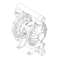
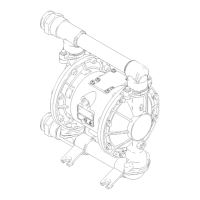
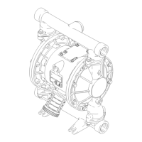
For Husky 1590 Aluminum and Stainless Steel Pumps, Series A
Repair Kits may be ordered separately. To repair the air valve, order Part No. 236273 for aluminum center housing
models or Part No. 255061 for stainless steel center housing models (see page 24). Parts included in the Air Valve
Repair Kit are marked with a symbol in the parts list, for example (3).
To repair your pump, select the six digits which describe your pump from the following matrix, working from left to
right. The first digit is always D, the second digit is always 0 (zero), and the third is always B. The remaining three
digits define the materials of construction. Parts included in the kit are marked with an asterisk in the parts list, for
example (201*). For example, if your pump has polypropylene seats, PTFE balls, and PTFE diaphragms, order
Repair Kit D 0 B 9 1 1. If you only need to repair certain parts (for example, the diaphragms), use the 0 (null)
digits for the seats and balls, and order Repair Kit D 0 B 0 0 1. The digits in the matrix do not correspond to the
ref. nos. in the parts drawing and lists on pages 24–25.
Diaphragm
Pump Null Shaft O-ring – Seats Balls Diaphragms
D (for all pumps) 0 (for all pumps) B (PTFE) – 0 (null) 0 (null) 0 (null)
– 1 (not used) 1 (PTFE) 1 (PTFE)
– 2 (not used) 2 (acetal) 2 (not used)
– 3 (316 sst) 3 (not used) 3 (not used)
– 4 (17–4 PH sst) 4 (440C sst) 4 (not used)
– 5 (TPE) 5 (TPE) 5 (TPE)
– 6 (Santoprene) 6 (Santoprene) 6 (Santoprene)
– 7 (Buna–N) 7 (Buna–N) 7 (Buna–N)
– 8 (Fluoroelastomer) 8 (Fluoroelastomer) 8 (Fluoroelastomer)
– 9 (polypropylene) 9 (not used) 9 (not used)
– A (PVDF) A (not used) A (not used)
– G (Geolast) G (Geolast) G (Geolast)