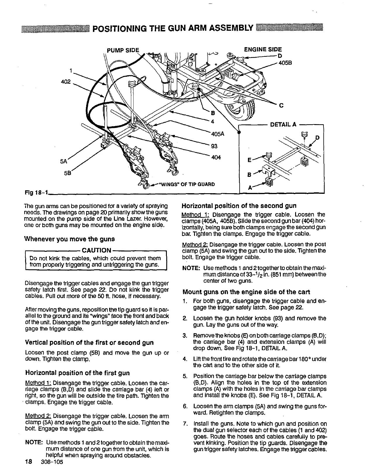
POSITIONING THE GUN ARM ASSEMBLY
Fig
18-1
1
402
DETAILA
-
rcWINGS"
OF
TIP
GUARD
'C
.\
@n
I
Horizontal
position
of
the second
gun
The
gun arms can be positioned for a variety of spraying
needs. The drawings on page
20
primarily showthe guns
mounted.on the pump side of the Line Lazer. However,
one or both guns may be mounted on the englne side.
Whenever
you
move
the
guns
CAUTION
Do not kink the cables, which could prevent them
from properly triggering and untriggering the guns.
Disengage the trigger cables and engage the gun trigger
safety latch first.
See
page 22. Do not kink the trigger
cables. Pull
out
more of the 50 ft. hose, if necessary.
Afler moving the guns, reposition
the
tip guard
so
It
is par-
allel to the ground and its "wings" face the
front
and back
of the unit. Disengage the gun trigger safety latch and en-
gage
the
trigger cable.
Vertical
position
of
the
first
or
second
gun
Loosen the post clamp (5B) and move the gun up or
down. Tighten the clamp.
Horizontal
position
of
the
first
gun
Method
1:
Disengage the trigger cable. Loosen the car-
riage clamps (B,D) and slide the carriage bar (4) left or
right,
so
the gun will be outside the tire path. Tighten the
clamps. Engage the trigger cable.
Method
2:
Disengage the trigger cable. Loosen the arm
clamp (5A) and swing the gun out to the side. Tighten the
bolt. Engage the trigger cable.
NOTE:
Use
methods
1
and
2
togetherto obtain the maxi-
mum distance of one gun from the unit, which is
18
308-105
helpful when spraying~around obstacles.
Method
1:
Disengage the trigger cable. Loosen the
clamps (405A,
405B).
Slide the second gun bar (404) hor-
izontally, being sure both clamps engage the second gun
bar. Tighten the clamps. Engage the trigger cable.
Method
2:
Disengage
the
trigger
cable.
Loosen
the
post
clamp (5A) and swing the gun
out
to
the side. Tighten the
bolt. Engage the trigger cable.
NOTE Use methods
1
and
2
together
to
obtain the maxi-
mum distance of
33-1/,
in.
(851
mm) between the
center of two guns.
Mount
guns
on
the
engine side
of
the
cart
1.
For both guns, disengage the trigger cable and en-
gage the trigger safety latch. See page 22.
2.
Loosen the gun holder knobs (83) and remove the
gun. Lay the guns out of the way.
3. Removethe knobs
(E)
on both carriage clamps (B.D);
the caniage bar (4) and extension clamps (A) will
drop down.
See
Fig
18-1, DETAIL
A.
4. Lift the front tire and rotate the carriage bar 1
80°
under
the Carl and
lo
the other side
of
it.
5.
Position the carriage bar below the carriage clamps
(B,D).
Align
the holes
in
the top of the extension
and install the knobs
(E).
See Fig
18-1,
DETAIL
A.
clamps
(A)
with the holes in the carriage bar clamps
6.
Loosen the arm clamps (5A) and swing the guns for-
ward. Retighten the clamps.
7.
Install the guns. Note to which gun and position on
the dual gun selector each of the cables
(1
and 402)
goes. Route the hoses and cables carefully to pre
vent kinking. Position the tip guards. Disengage the
gun trigger safety latches. Engage the trigger cables.
 Loading...