DISPLACEMENT
PUMP
WAANiNG
To
reduce the risk of serious
bodily injury from pump rupture.
use
only
tool 226-586 to
re-
stuck, send the cylinder to your
Graco distributor for removal.
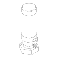
6.
Remove the sleeve when
servicing the pump.
Use spe-
cial tool, Part No. 226-586
only. Screw the nut
(B)
into 219 flg
27-3
the cylinder (219). screw
down the rod
(A)
to push the
sleeve out.
See
Fig 27-1.
~l~
27-1
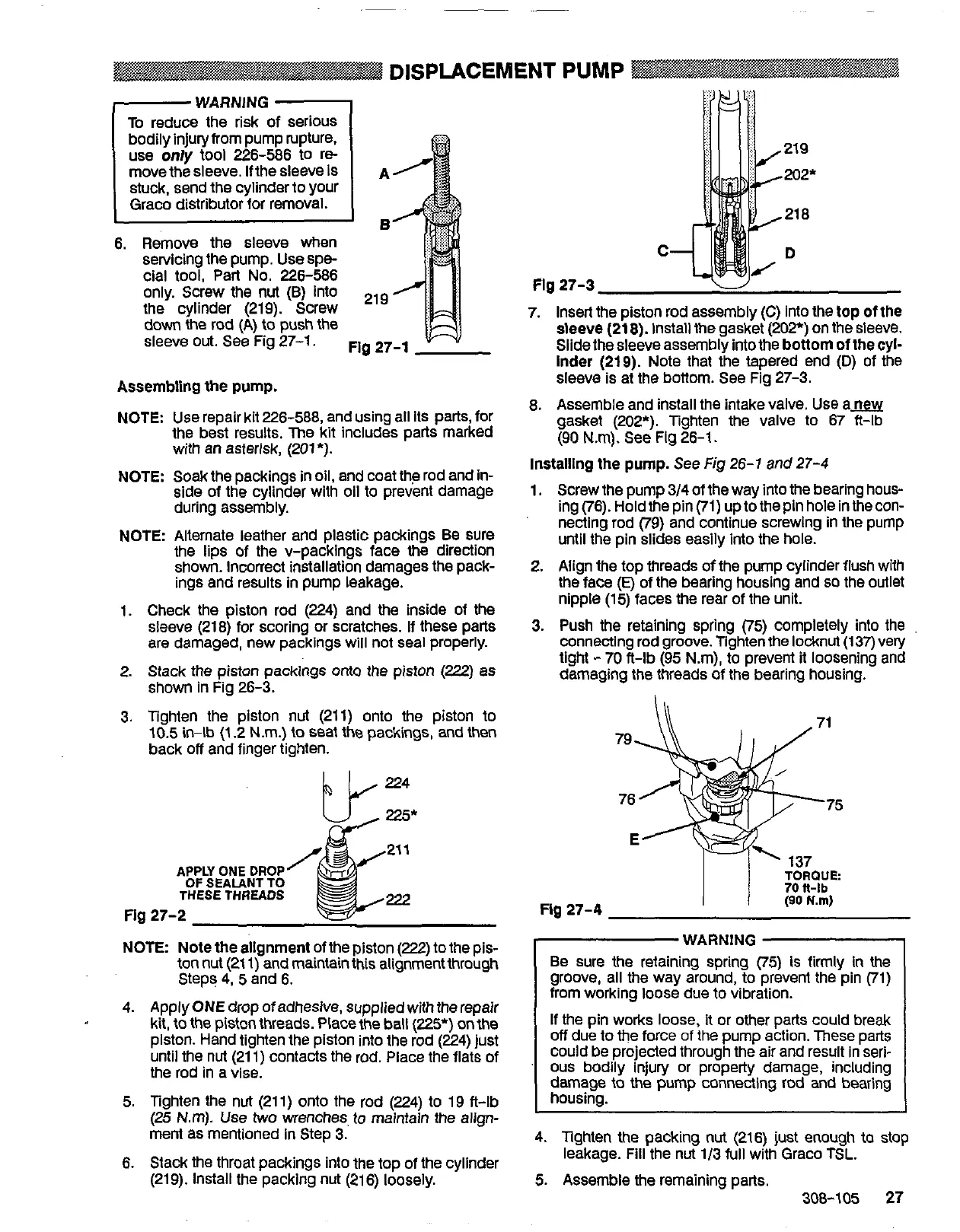
7. Insert the piston rod assembly
(C)
into the top of the
sleeve
(21
8).
install the gasket
(202'9
on the
sleeve.
Slide the sleeve assembly into the
bottom
of the cyi-
lnder
(219).
Note that the tapered end
(D)
of
the
sleeve is at the bottom.
See
Fig 27-3.
Assembling
the
pump.
NOTE:
Use
repair kit 226-588, and using all its parts, for
the best results.
me
kit Includes parts marked
with an asterisk, (201*).
NOTE: Soak the packings in oil, and coat
the rod and in-
side of the cylinder with oil to prevent damage
during assembly.
NOTE Alternate leather and plastic packings
Be
sure
the lips
of
the v-packings face
the
direction
shown. Incorrect installation damages the pack-
ings and results in pump leakage.
1. Check the piston rod (224) and
the
inside of
the
are damaged, new packlngs will not seal properly.
sleeve (218) for scoring or scratches.
If
these parts
2. Stack the piston packings
onto
the piston
(222)
as
shown in Fig 26-3.
3.
Tighten the piston
nut
(211) onto the piston to
10.5 in-lb (1.2 N.m.) to Seat the packings, and then
back
off
and finger tighten.
21
1
APPLY
ONE
DROP
OF
SEALANT TO
THESE
THREADS
Flg
27-2
222
8. Assemble and install the intake valve.
Use
am
gasket (202*). Tighten the valve to 67 ft-lb
(90 Nm).
See
Fig 26-1.
Installing the pump. See
Fig
26-1
and
27-4
1. Screw the pump 3/4 of the way into the bearing hous-
ing
(76).
Hold the pin
(71)
up to the pin hole In the con-
necting rod
(79)
and continue screwing in the pump
until the pin slides easily into the hole.
2. Align the top threads
of
the pump cylinder flush with
the face
(E)
of the bearing housing and
so
the outlet
nipple (15) faces
the
rear of the unit.
3. Push the retaining spring
(75)
completely into the
Connecting rod groove. Tighten the locknut
(137)
very
light
-
70
ft-lb (95 Nm), to prevent
it
loosening and
damaging the threads
of
the bearing housing.
.-.
TORQUE
Fig
27-4
(90
N.m)
NOTE Note the allgnment of the piston
(222)
to the pis-
ton nut (21
1)
and maintain this alignment through
Steps
4,
5
and
6.
4. Apply ONE drop of adhesive, supplied with the repair
kit, to the piston threads. Place the bail
(225*)
on the
piston. Hand tighten the piston into the rod (224) just
until the nut (21 1) contacts the rod. Place the flats of
the rod in a vise.
5. Tighten the nut (21 1) onto the rod (224)
to
19 fl-lb
(25
N.m).
Use
two
wenches.
to
maintain the align-
ment as mentioned in Step
3.
6.
Stack the throat packings into the top of the cylinder
(219). Install the packing nut (216) loosely.
Be
sure
the
retaining spring
(75)
is
firmly In
the
groove, all the way around, to prevent the pin (71)
from working loose due to vibration.
If
the pin works
loose,
it or
other
parts could break
off
due to the force
of
the pump action. These parts
could
be
projected through the air and result in
seri-
ous
bodily injury or property damage, including
damage to the pump connecting rod and bearing
housinQ.
4.
Tighten
the
packing nut (216)
just
enough to stop
5.
Assemble the remaining parts.
leakage. Fill the nut 1/3 full with Graco TSL.
308-105
27
 Loading...