~~
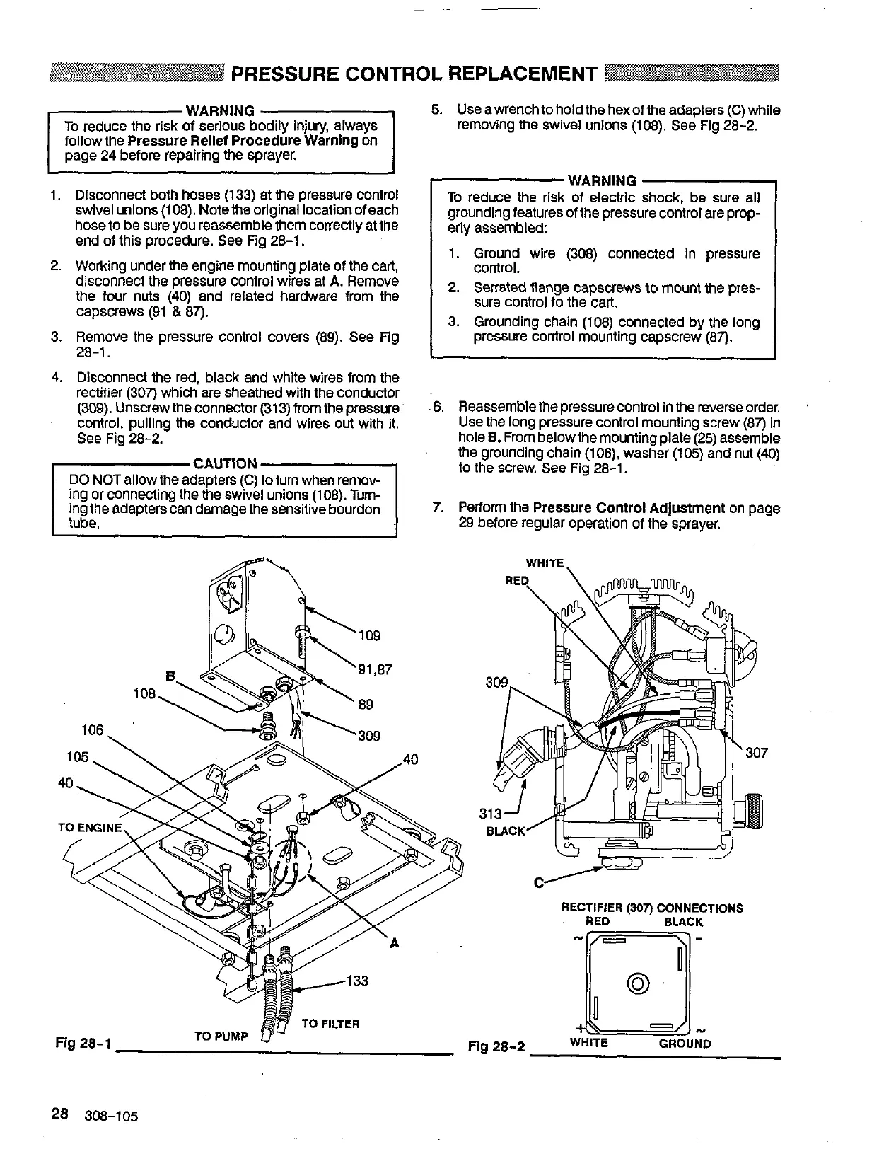
~~~~~~~~ PRESSURE CONTROL REPLACEMENT
followthe
Pressure Rellef Procedure Warning
on
page 24 before repairing the sprayer.
5.
Use
a wrench to hold the hex of the adapters (C) while
removing the swlvel unions (108).
See
Fig 28-2.
1.
2.
3.
4.
Disconnect both hoses (133) at the pressure control
swivel unions (108). Notethe original locationofeach
hose to be sure you reassemble them correctly at the
end of this procedure.
See
Fig 28-1.
Working under the engine mounting plate of
the
cart,
disconnect the pressure control wires at
A.
Remove
the four nuts
(40)
and related hardware from the
capscrews (91
&
87).
Remove the pressure control covers (89).
See
Fig
28-1.
Disconnect the red, black and white wires from the
rectifier (307) which are sheathed with the conductor
(309).
Unscrew the connector (31
3)
from the pressure
control, pulling the conductor and wires out with it.
See
Fig 28-2.
ing or connecting the the swivel unions (108). Tum-
DO
NOT
allow
the
adapters (C) to tum when remov-
ing the adapters can damagethe sensitive bourdon
WARNING
To
reduce the risk of electric
grounding features of the pressure control are prop-
erly assembled:
1. Ground wire (308) connected In pressure
control.
2.
Serrated flange capscrews
to
mount
the pres-
sure control to the cart.
3. Grounding chain (106) connected by the long
pressure control mounting capscrew (87).
I
I
6.
7.
Reassemble the pressure control
in
the reverse order.
Use
the long pressure control mounting screw
(87)
in
the grounding chain (106). washer (105) and nut
(4)
hole
B.
From belowthe mounting plate
(25)
assemble
to the screw. See Fig 28-1.
Perform
the
Pressure Control Adjustment
on page
29
before regular operation of the sprayer.
WHITE,
RECTIFIER
(307)
CONNECTIONS
RED BLACK
28 308-105
 Loading...