PRESSURE
CONTROL CALIBRATION
WARNING
USE EXTREME CAUTION WHEN PERFORMINGTHIS CALIBRATION PROCEDUREto reducethe riskof afluid
injection injury
w other serious bodily injury, which can resuit from component rupture, electric shock, fire, expio-
slon or moving parts.
This procedure sets the sprayer to 2600-3000 psi NEVER attempt to increase the fluid outlet pressure by
1182-210 barl MAXIMUM WORKING
PRESSURE.
oerformina these calibrations
in
anv other wav. NEVER
~~
,
~ ~~~~ ~
~.
I
Perfo~~his procedure whenever the Dressure control PRESSURE. Normal ooeration of the soraver at hioher
'U(CEED
5000
PSI
(210
BAR)
M~IMUM
WORKING
assembly is'removed and reinstalled; or replaced, to
pressures could
res&
in component'rui;ture,
ti&
or
be sure the sprayer
Is
properly calibrated.
explosion.
pressurize and result in component rupture, fire or
ex-
for at least 3000 PSI (210 BAR) MAXIMUM WORKiNG
Improper calibration can cause the sprayer to over- ALWAYS
use
a
new50
foot (15.2
m)
spray hose, rated
the maximum working pressure, resulting
in
poor
under-rated hose could develop a high pressure leak
plosion. It may also prevent the sprayerfrom obtaining PRESSURE, when pelforming this procedure.
A
used,
sprayer performance.
or rupture.
~~ ~ ~ ~~
Service Tools Needed:
NEW
50
foot
(15.2
m).
3000
psi
(210 bar),
flexible nylon airless spray hose,
Pari
No.
223-541
0-5000 psi
(0-350
bar) fluid-filled pressure gauge,
NEW spray tip, size 0.025 to
0.029
Part
No.
102-814
3/8
in.
ignition wrench
or
nut
driver
5
gallon pail
of
water or mineral splrits
Swivel, 156-823
Nipple, 162-453
e
Tee. 104-984
Set Up
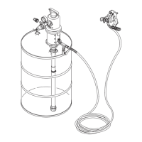
1. Follow the Pressure Relief Procedure Warning
on
2.
Set up the system as shown in Fig 29-1.
Set the Dead Band (Pressure Differential)
1. Remove the pressure control cover.
NOTE
Do
not alterthis adjustment ifthewheel
is
already
page
24.
set as shown
in
Fig
29-2.
2.
Set the white differential wheel
(A)
on the micro-
switch.
Turn
the wheel
so
the letter
F
is
concealed be
hind the switch and the letter
E is the first letter seen.
Pressure Up
1.
Start the sprayer and
prime
it.
2.
Adjust the pressure to
2600
psi
(180
bar),
3.
Shut
off
the engine.
If
the pressure drops after the en-
gine is shut
on,
replace the pump packings before
proceeding.
See
page
26.
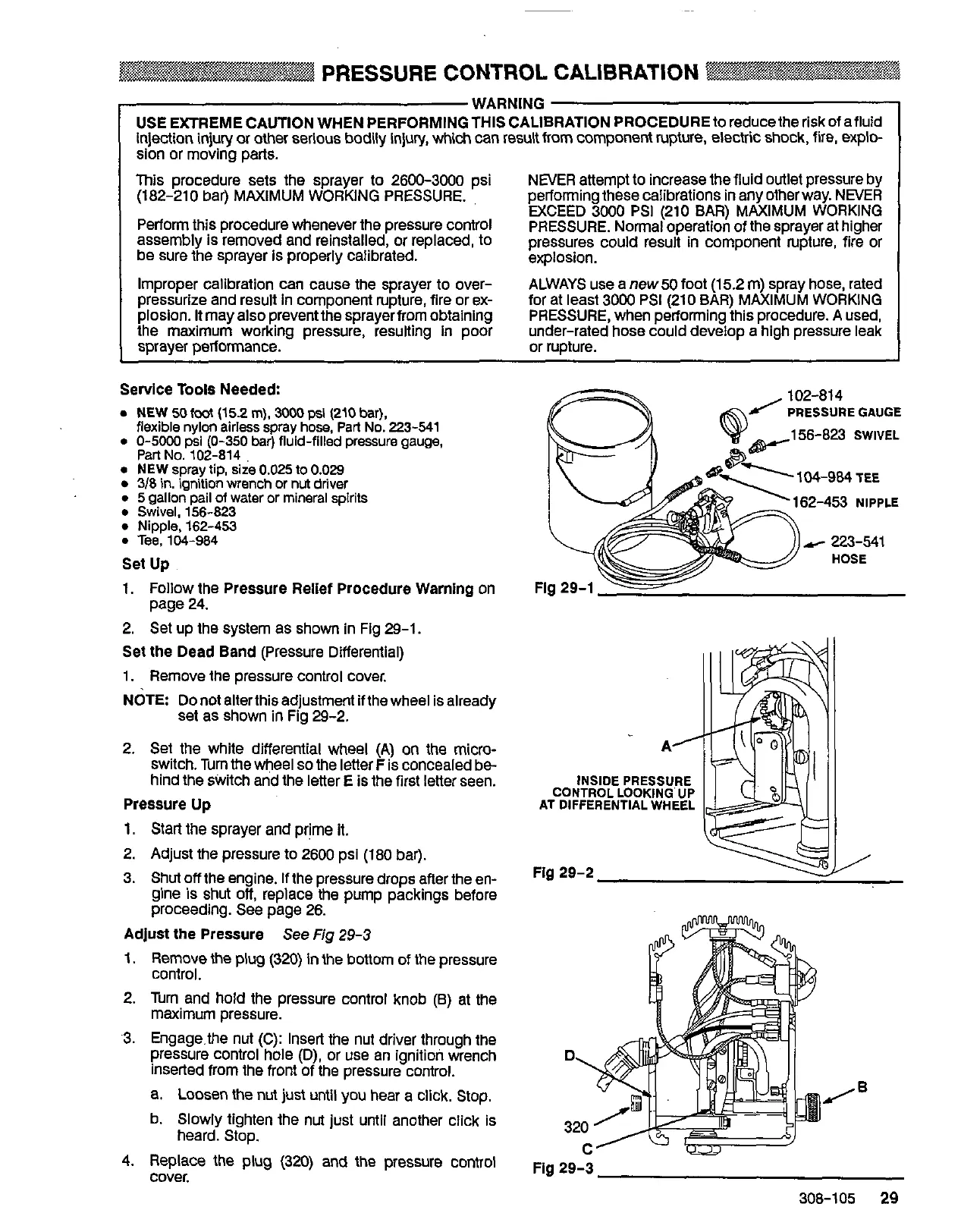
Adjust the Pressure
See
Fig
29-3
1.
Remove the
plug
(320)
in
lhe bottom
of
the pressure
control.
2.
Turn and hold the pressure control knob (6) at the
maximum pressure.
.3. Engage.the nut (C): Insert the nut driver through the
pressure control hole (D), or use an ignition wrench
Inserted from the front of the pressure control.
a.
Loosen
the
nut
just until you hear a click, Stop.
b. Slowly tighten the nut just until another click is
heard. Stop.
4.
Repiace the
plug
(320) and the pressure control
cover.
PRESSUREGAUGE
156-823
SWIVEL
162-453 NIPPLE
Y
223-541
HOSE
Fig
29-3
308-105
29
 Loading...