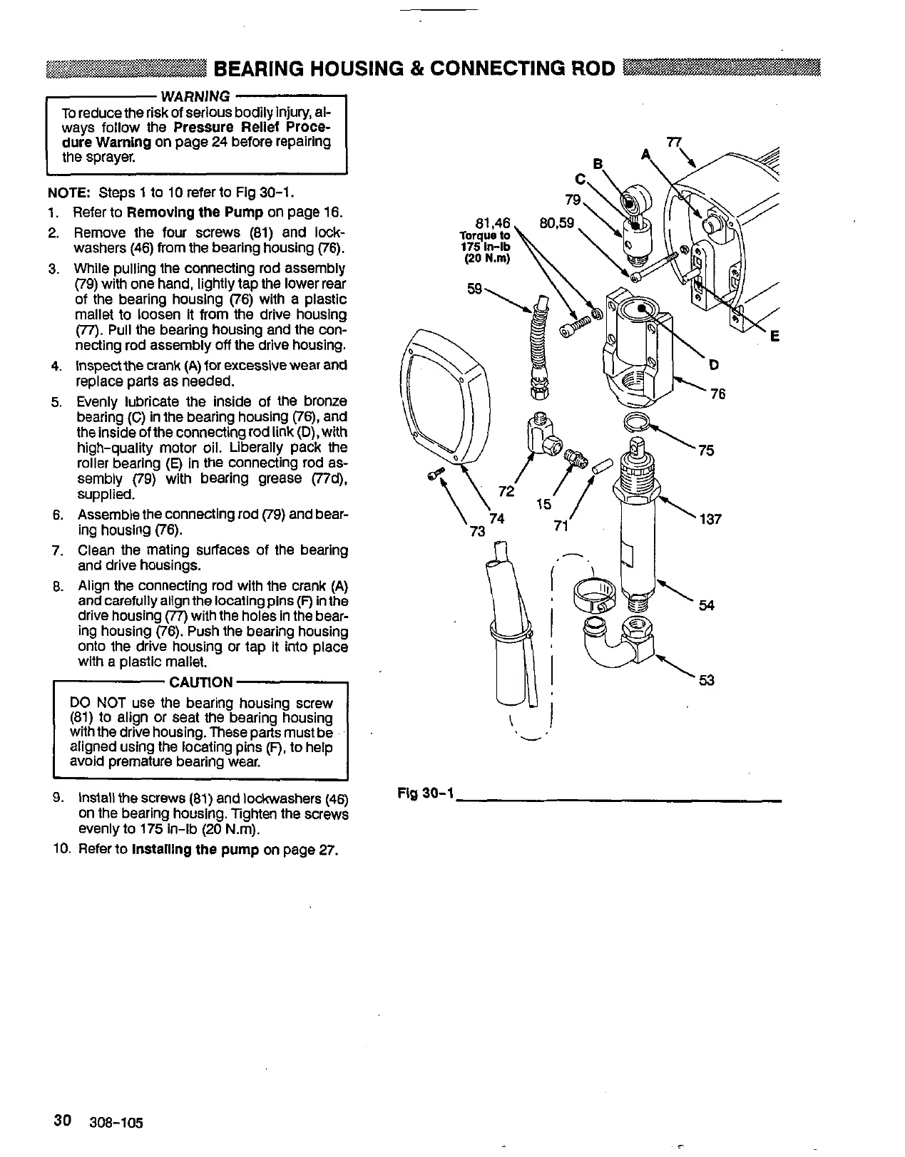
BEARING HOUSING
&
CON.NECTlNG
ROD
WARNING
dure Warning on page
24
before repairing
NOTE
Steps
1
to
10
refer to Fig
30-1.
1.
Refer to Removing the Pump on page
16.
2. Remove the four screws
(81)
and lock-
washers
(46)
from the bearing housing
(76).
3.
While pulling the connecting rod assembly
(79)
with one hand, lightly tap the lower rear
of the bearing housing
(76)
with a plastic
mallet to loosen it from the drive housing
necting rod assembly
off
the drive housing.
(77).
Pull
the bearing housing and the con-
4.
Inspect the crank (A) for excessive wear and
replace parts as needed.
5.
Evenly lubricate the inside of the bronze
the inside of the connecting rod link
(D),
with
bearing
(C)
in
the bearing housing
(76),
and
high-quality motor oil. Liberally pack the
roller bearing
(E)
in the connecting rod
as-
sembly
(79)
with bearing grease (Tld),
supplied.
6.
Assemble the connecting rod
(79)
and bear-
ing housing
(76).
7.
Clean the mating surfaces of the bearing
and drive housings.
8.
Align the connecting rod with the crank (A)
and carefully align the locating pins
(F)
in the
drive housing
(77)
with the holes in the bear-
ing housing
(76).
Push the bearing housing
onto the drive housing or tap it into place
with
a
plastic mallet.
.,
u
9.
Install the screws
(81)
and lockwashers
(46)
on the bearing housing. Tighten the screws
evenly to
175
in-lb
(20
N.m).
~~
Fig
30-1
10.
Refer to Installing the pump on page
27.
30
308-105
 Loading...