7308-262
Installation
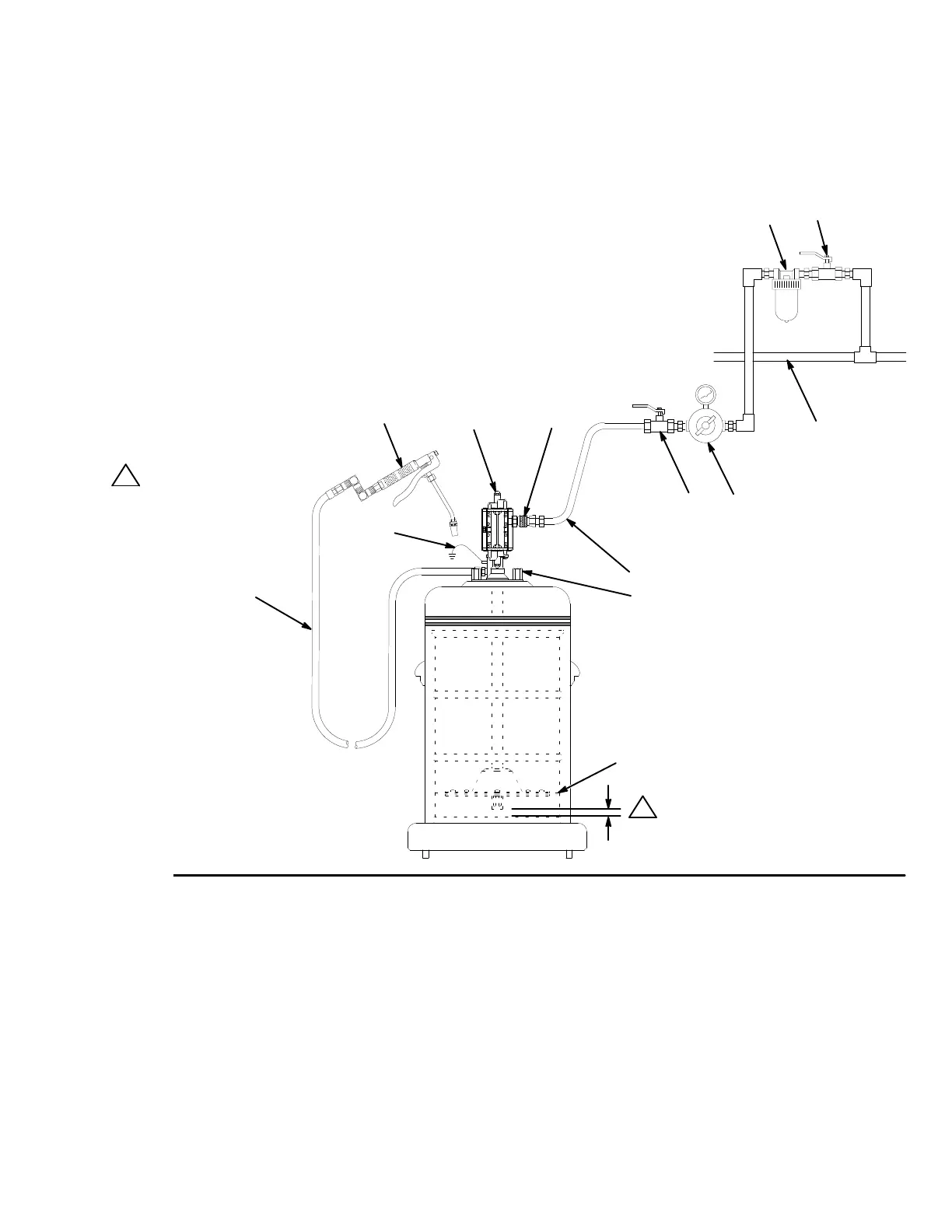
The T
ypical Installation shown in Fig. 3 is only a guide for selecting and installing system components and
accessories. Contact your Graco distributor for assistance in designing a system to suit your particular needs.
If you supply your own accessories, be sure they are adequately sized and pressure-rated to meet the system’
s
requirements. See the
Maximum W
orking Pressure
warning on page 8.
Fig. 3
A
BC
KEY
A Pump
B Bleed-type
master air valve (required)
C
Air regulator
D
Air hose
E
Air line quick disconnect
F
Air line filter
G
Bleed-type master air valve (for accessories)
H
Main air line
J
Gun holder
K
Follow plate
L
Fluid hose
M
Dispense valve
Y
Ground wire (required)
01967
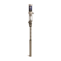
Model
235–889 Pump,
shown mounted on movable cart
D
E
FG
H
J
K
L
M
Y
The
pump intake
should be no more
than 1/2
in. (13 mm)
of
f the bottom of the
fluid container
.
1
1