~~ ~
~
REMOVING
and
REPLACING PRESSURE CONTROL
I
,
..
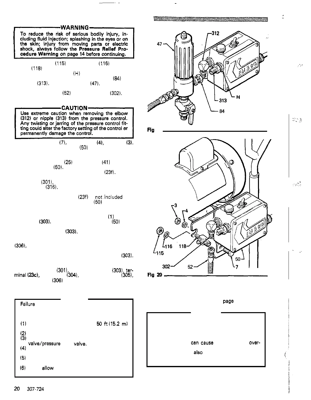
adapter (118) holding the filter to the mounting bracket.
Remove the nut
(115) and washer (116) from the
with
a
wrench and unscrew the swivel union
(84)
from
See
Fig
20.
Hold the nut
(H)
at
the pressure control
the nipple
(313). Remove the filter (47).
See
Fig 19.
Disconnect the hose
(52) from the nipple 1302).
See
Fig
20.
Remove the screws (7), lockwashers
(4),
and nuts
(3).
Remove the pressure control
(50)
from the frame.
See
Fig
20.
Remove the screws
(25)
and cover (41) from the
pressure control
(50).
Disconnect the red, pink and
brown motor leads from the circuit board
(23f). Discon-
nect the green and yellow motor lead from the groun
-
ding screw (3011, and the black motor lead from the
toggle switch
(316). See Fig 21.
NOTE:
The circuit board
(23f)
is
not.included with
the pressure control
(50)
replacement
assembly. Order separately if needed.
connector
(303).
Pull
the pressure control
150)
away
Unscrew the nut on the end of the conduit
(1) from the
from the conduit while carefully guiding the wires
through
the
connector
(303).
See
Fig 21.
Loosen the knurled pert of the power cord strain relief
the strain relief up on the power cord to provide
(306).
and unscrew
it
from the pressure control. Slide
clearance, and unscrew the conduit connector
(303).
See
Fig
21.
Remove
the
screw
(301).
conduit connector (303). ter-
and strain relief (306) from the old pressure control.
mind 123c), lockwasher
1304).
power supply cord
(305).
Replace any damaged parts. Assemble these parts to
the new pressure control.
CAUTION
Failure to observe the following may cause poor
performance or excessive pressure end permanent
damage to the pressure control:
(1)
Always use nylon spray hose
et
50
ft
(15.2 m)
(2)
Never
use
a wire braid spray hose.
13) Never attach
a
spray hose to the filter drain
(4) Never add any type of shut
off
device between
valve/pressure relief velve.
(5)
Be
sure to check filter for clogging or incorrect
the pump outlet and the spray gun.
(6)
Never ellow flushing water or water base paint
assembly if tip clogging frequency increases.
to freeze in the system.
minimum length.
20
307-724
Fig
19
Replace in the reverse order of disassembly and then
calibrate the pressure control.
See
pege
22.
WARNING
whenever
a
new or used microswitch or pressure
The pressure control
MUST
be calibrated
control assembly
is
removed and reinstalled or
replaced to be sure the control is properly
calibrated. Failure to properly calibrate the
pressure control
can cause the sprayer to over-
explosion.
It
may
also
prevent the sprayer from
pressurize end result in component rupture, fire or
obtaining
the
maximum working pressure which
would result in poor sprayer performance.
.
,
,::1
..
..
.....
..'.,
,:)'
..
......
4
..
.
,.
..<.,.>
.. .
. .
..
 Loading...