WARNING
To
reduce the risk of serious bodily injury, always fol-
page
13
before repairing the sprayer.
low the Pressure Relief Procedure Warning on
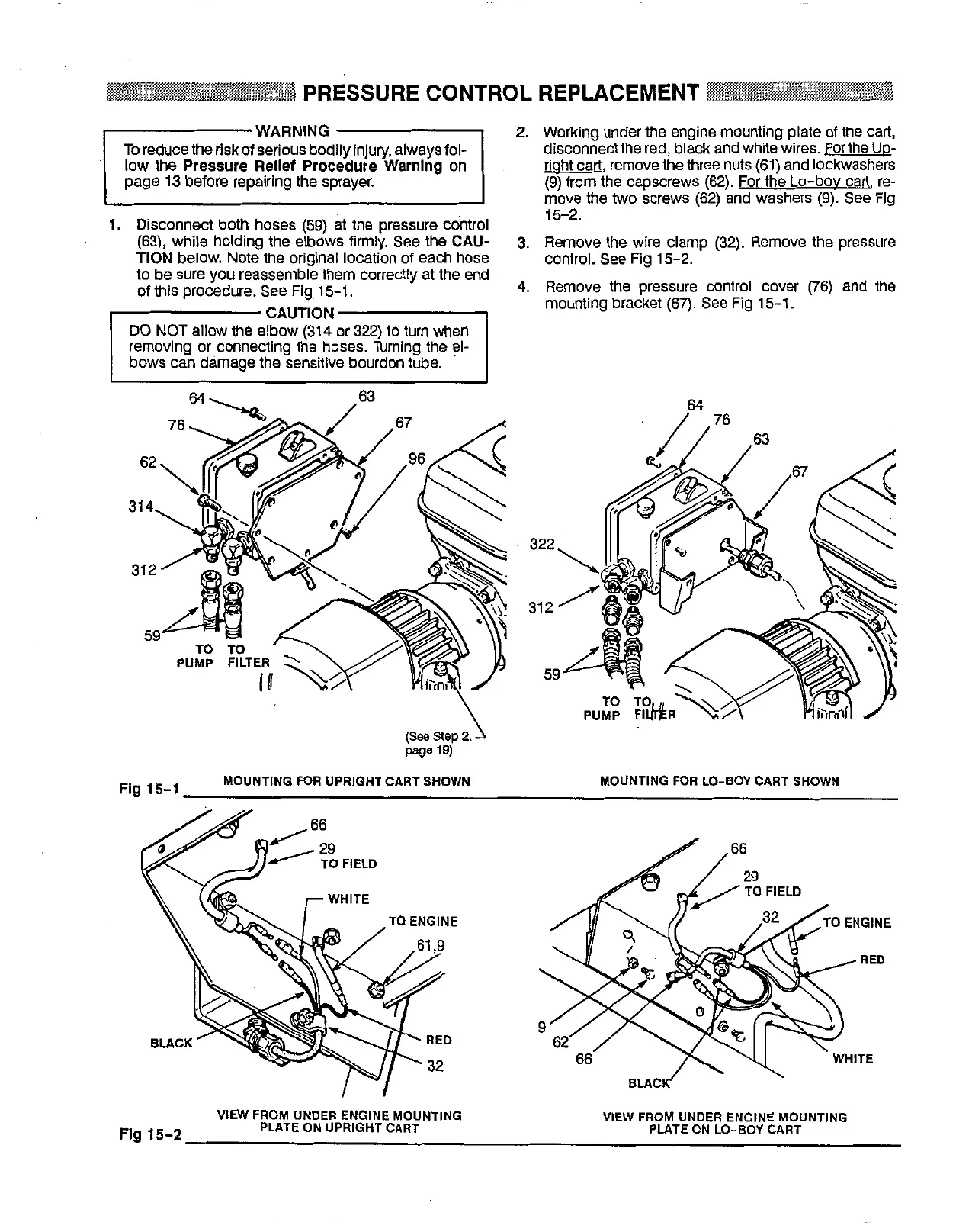
1.
Disconnect both hoses
(59)
at the pressure control
TlON below. Note the original location of each hose
(63),
while
holding the elbows firmly.
See
the CAU-
to be sure you reassemble them correctly at the end
of
this procedure.
See
Fig
15-1.
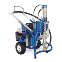
2.
Working under the engine mounting plate of the cart,
riaht cart, remove the three nuts
(61)
and lockwashers
disconnect the red, black and white wires. Forthe
UD-
move the
two
screws
(62)
and washers
(9).
See
Fig
(9)
from the capscrews
(62).
For the Lo-bov cart, re-
3.
Remove the wire clamp
(32).
Remove the pressure
4.
Remove the pressure control cover
(76)
and the
15-2.
control.
See
Fig
15-2.
mounting bracket
(67).
See
Fig
15-1.
/
76
64
page
19)
Fig
15-1
MOUNTING
FOR
UPRIGHT
CART
SHOWN
MOUNTING
FOR
LO-BOY
CART
SHOWN
TO
ENGINE
Flg
15-2
VIEW
FROM
UNDER ENGINE
MOUNTING
PLATE
ON
UPRIGHT
CART
VIEW
FROM
UNDER
ENGINE
MOUNTING
PLATE
ON
LO-BOY
CART