Wire Pattern Control Board
20 334784G
Encoder Installation
(PC-8e only)
1. Connect up to two encoders to monitor line speed.
NOTE: Line 1 and line 2 on the ADM.
NOTE: Encoder type must be quadrature differential
line driver (RS422). Scaling is entered in the
encoder setup screen using the live calibration fea-
ture.
NOTE: Some encoders have Z and Z’ connections.
These are not used and do not need to be con-
nected.
NOTE: Encoder direction can be reversed by swap-
ping A and A’ with B and B’. Do this is the line speed
reads negative on the ADM.
Run Up Installation (PC-8e only)
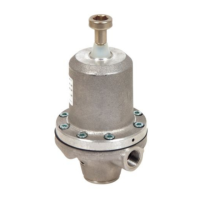
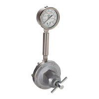
1. Connect up to two “I/P” or “V/P” run-up air pressure
regulators to vary pump pressure based on line
speed. Hardware automatically detects whether an
I2P or V2P is connected.
NOTE: Pressure vs. line speed settings are entered
on the run-up setup screen. See Run Up Control,
page 42.
Graco Encoder Wiring Diagram
Terminal Function Wire Color
Plus 15V Supply Red
A Phase A signal
(RS422)
Brown
A’ Phase A signal return White
B Phase B signal
(RS422)
Yellow
B’ Phase B signal return Green
Minus (-) Return Blue
PE Shield Bare
Standard Wire Colors
Terminal Function M12 Cable
Plus (+) 24V Supply Brown
% Output to run-up Black
Minus (-) Return Blue
Minus (-) Return White

 Loading...