
P
prestonwarnerSep 23, 2025
Why is there no power to my Graco InvisiPac Tank-Free HM25 Industrial Equipment unit?
- AAngela Long MDSep 23, 2025
Check that the main power breaker is turned on and that the power plug is connected.
Why is there no power to my Graco InvisiPac Tank-Free HM25 Industrial Equipment unit?
Check that the main power breaker is turned on and that the power plug is connected.
What to do if my Graco InvisiPac Tank-Free HM25 Industrial Equipment pump is running away?
If the Graco Industrial Equipment pump is running away, it could be due to several reasons. First, check if the storage bin is out of adhesive and refill if necessary. Also, ensure the melter temperature is set correctly, according to the manufacturer's recommendations. Additionally, inspect the vacuum transfer hose or funnel for any blockages and clear them. Finally, examine the pump seals for wear or damage and repair them if needed.
What causes pump diving in Graco InvisiPac Tank-Free HM25 and how to fix it?
If the Graco Industrial Equipment pump is diving, it may be due to the storage bin being out of adhesive pellets; refill the bin. Also, the melter might be at an incorrect temperature, too low, so check the temperature setting and adjust it to the manufacturer's recommendation. A plugged vacuum transfer hose or funnel can also cause this, so clear any blockages. Additionally, check if the feed rate for dispensing is too high. Lastly, inspect the pump seals for wear or damage, and repair if necessary.
How to troubleshoot vacuum transfer not working in Graco InvisiPac Tank-Free HM25 Industrial Equipment?
If the vacuum transfer is not working on your Graco Industrial Equipment, first verify the vacuum transfer system air pressure is within 40-80 psi (60 psi recommended). Next, check that the air line is connected and not pinched, if air is at the system air gauge but not to the air shaker. If air is at the shaker but there is no feed, a plugged shaker unit may be the cause. Remove the shaker from the system and remove the plug.
What causes no current to the melter in Graco InvisiPac Tank-Free HM25?
If there's no current to the melter in your Graco Industrial Equipment, check fuses F1 and F2 on the MZLP with the daughter board. Also, ensure that J1 is plugged into the MZLP with the daughter board. The system also requires a hose connected to Channel 1 or the use of the optional Overtemperature Jumper, 16Y727.
How to troubleshoot a fill solenoid error on Graco InvisiPac Tank-Free HM25?
If you encounter a Fill Solenoid Error on your Graco Industrial Equipment, verify the wiring between J13 and the refill solenoid is not damaged. Restart the system.
How do I fix a cycle switch error on Graco InvisiPac Tank-Free HM25 Industrial Equipment?
If you're experiencing a cycle switch error on your Graco Industrial Equipment, it could be due to no signal from the air motor sensor. Check the wiring on J16 of the daughter board. Also, check for a loose cycle switch bolt and tighten it. If those steps don't solve the problem, consider replacing the cycle switch.
What does it mean when my Graco Industrial Equipment says 'Missing DB'?
If the Graco Industrial Equipment is showing a missing DB error, it means the system is not acknowledging the daughter board. This could be due to a bad connection between the daughter board and the MZLP board. Loosen the daughter board, re-seat it, then secure it. If the MZLP daughter board does not respond to adjustment, replace the daughter board.
How to troubleshoot high current in a Graco InvisiPac Tank-Free HM25 melter?
If the Graco Industrial Equipment melter is showing high current, measure the resistance to ground between the heater leads. Replace the band heater or rod heater if needed.
What should I do if there's unexpected current in gun X of my Graco InvisiPac Tank-Free HM25 Industrial Equipment?
If you are seeing unexpected current to gun X on your Graco Industrial Equipment, it could be due to unexpected current flow to gun X. Replace the MZLP. Also, check heater resistance and resistance to ground, and replace the heater if necessary.
Ensures proper electrical connection to reduce shock hazard.
Specifies ambient temperature and placement requirements for system components.
Details steps for connecting hoses, funnels, and other system parts.
Guidelines for installing a transformer for 480V supply and sizing calculations.
Recommendations for installing a transformer for 208V supply.
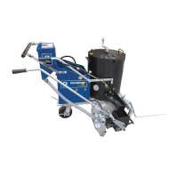
Describes the system's function of pulling, melting, pumping, and dispensing adhesive.
Steps to prepare the system for its first use, including filling and powering on.
Steps to inspect and replace the filter preventing contaminants from entering hoses and guns.
Procedure for replacing the filter that prevents large items from entering the system.
Lists ADM error codes, their meaning, and potential causes and solutions.
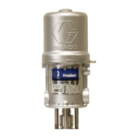
Detailed procedures for replacing seals, bearings, and rod in the pump assembly.
Steps for identifying and replacing fuses on the MZLP module.
Steps to remove and replace the solenoids in the air control assembly.
Instructions for removing and installing the air control gauge.
Details on connecting incoming power and setting terminal jumpers based on phase and voltage.
List of parts for the InvisiPac system, covering the first part of the assembly.
Tools designed for system repairs to prevent part damage.
Steps to place and secure the system on the stand.
Instructions for installing the adapter plate to replace existing applicator systems.
How to install the jumper to run the melter without a hose/gun.
Steps to install a strain relief bushing for smaller diameter power cords.
Explains ADM power, screen navigation, and enabling/disabling the heating system.
Identifies icons used in Operation, Setup, and Schedule screens for user interaction.
Shows actual temperatures of the system melter and each gun and hose.
Allows editing temperature settings for the system melter, guns, and hoses.
Explains the Events screen for viewing system logs and error codes.
How to set automatic ON/OFF times for heating and pump operation.
Settings for language, date, time, password, and screen saver.
Settings for temperature, mass, and distance units.
Steps to download system settings, logs, and language files via USB.
Procedure for installing system configuration or custom language files via USB.
Overall physical dimensions of the InvisiPac system.
Specifications for mounting the system to a wall.
| Model | InvisiPac Tank-Free HM25 |
|---|---|
| Category | Industrial Equipment |
| Output Rate | 25 lb/hr (11.3 kg/hr) |
| Number of Guns Supported | Up to 2 |
| Power Supply | 200-240 VAC, 50/60 Hz, 1 Phase |
| Viscosity Range | Up to 20, 000 cP |
| Weight | 85 lb (38.6 kg) |