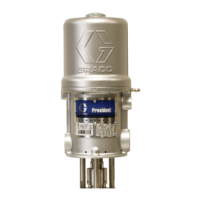
Setup
3A2347ZAA 23
PLC Connection
A PLC can control and monitor all items shown in the
dropdown menus on the System 1 screen in the Setup
screens.
Customer Input Dropdown Options
Customer Output Dropdown Options
NOTE: All outputs are normally open when power is
OFF. For Error (Alarm) output, the contacts open when
an alarm occurs. For all others, contacts close.
NOTE: The InvisiPac system ships with two
screw-terminal connectors that plug into MZLP
connectors H1 and H2. Connectors are located in a bag
on the inside of the electrical enclosure front access
door. To replace the connectors, order kit 24P176.
1. On the System 1 screen (in the Setup screens) select
the function of each input on MZLP connector H1 and
each output on MZLP connector H2.
2. Turn main power switch OFF.
3. Remove electrical enclosure front access door.
4. Route I/O cable through strain relief in electrical
enclosure. See Customer I/O Cable (S) in FIG.1on
page 8.
5. Remove power from PLC.
6. Connect the PLC to connectors H1 and H2.
NOTE: Each connector has four signals. The MZLP
board specifies the input range for each signal. See the
following table for pin assignments.
Inputs: High: 10-30 Vdc, Low: 0-5 Vdc. Inputs function
without concern for polarity. Applying “high” voltage will
turn the heaters on and enable channels. Removing volt-
age will turn the heaters off and disable channels.
Outputs: 0-250 Vac, 0-30 Vdc, 2A.
Option Description
Disable Not used.
Heater On/Off Turn on or off the heating system and
pump.
Channel 1, 2, 3,
or 4 Enable/Dis-
able
Enable or disable hose and gun heat-
ing for that individual channel.
Option Description
Disable Not used.
System Ready Indicates when the system is up to tem-
perature and the pump is stalled at
pressure.
Error (Alarm) Indicates when there is an active alarm.
An active alarm will disable the heating
system and pump.
Error (Devia-
tion/Advisory)
Indicates when there is an active devia-
tion or advisory. An active deviation or
advisory will NOT disable the heating
system and pump.
Maintenance Due Indicates when the maintenance total
has reached the preset notification
value.
FIG. 16: MZLP Board
H1 - Customer Input H2 - Customer Output
Signal Pin Signal Pin
1 1,2 1 1,2
2 3,4 2 3,4
3 5,6 3 5,6
4 7,8 4 7,8
J1
J2
J3
J6
J5
J7
F10
F9
F8
F7
F6
F5
F4
F3
F2
F1
H1
H2
 Loading...