EasyManuals Logo

Graco Magnum X5 Repair And Parts

Graco Magnum X5
52 pages
To Next Page IconTo Next Page
To Previous Page IconTo Previous Page
Page #46 background imageLoading...
Page #46 background image
Wiring Diagrams
46 312667K
Wiring Diagrams
X5 and X7 Models 262800 and 262805 (Series A)
7)2).'$)!'2!-
7()4%
"/!2$7)2%
!54/02)-%
0/7%2#/2$
",!#+7)2%
",!#+
-/4/2
,%!$
0/7%2#/2$
7()4%7)2%
",!#+
-/4/2
,%!$
!&53%
0/7%2#/2$
'2%%.7)2%
#(!33)3
'2/5.$
/./&&
37)4#(
02%3352%
37)4#(
Thermal Switch
1
1
When assembling motor to pump housing, make sure
Thermal Switch is positioned on top as shown above.
ti11322c
Ref 67a

Other manuals for Graco Magnum X5

Questions and Answers:

Question and Answer IconNeed help?

Do you have a question about the Graco Magnum X5 and is the answer not in the manual?
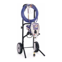
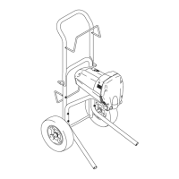
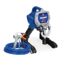
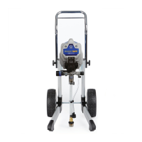
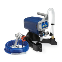
Graco Magnum X5 Specifications

General IconGeneral
TypeAirless Paint Sprayer
Maximum Flow Rate0.27 gallons per minute
Maximum Tip Size0.015 inch
Maximum Operating Pressure3000 PSI
Power SourceElectric
Voltage120V
Maximum Hose Length75 ft
Pressure ControlAdjustable
Recommended Annual Use125 gallons per year
Motor0.5 HP

Related product manuals