Motor Control Board
3A2244A 21
Motor Control Board
Removal
1. Turn power OFF. Wait 5 minutes for power to dissi-
pate. Perform Pressure Relief Procedure, page 9.
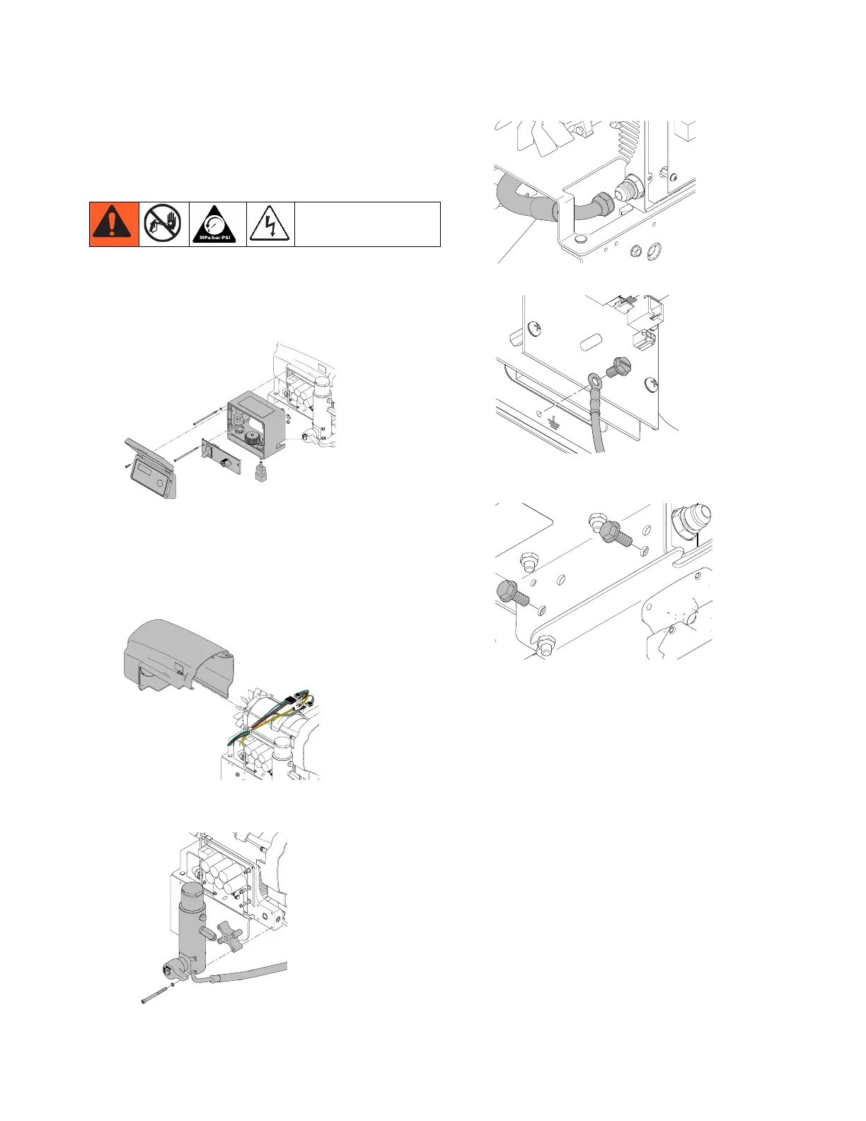
2. Remove display, control panel, and control box.
3. Disconnect display, 10/16 Amp switch, potentiome-
ter, pressure transducer, and fast flush connection
(if supplied). See Wiring Diagrams, page 34.
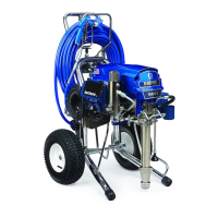
4. Remove motor shroud. Disconnect wires on top of
motor.
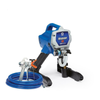
5. Remove four screws from front of filter bowl, then
remove filter bowl assembly and spacer.
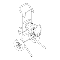
6. Remove hose from power bar.
7. Remove ground wire from control board assembly.
8. Remove two screws from underneath sprayer plat-
form to remove control board assembly.
Installation
1. Attach control board assembly to the frame. Torque
to 25 - 30 ft-lb (34 - 41 N•m).
2. Attach ground wire to assembly. Torque to 22 - 28
in-lb (2.5 - 3.2 N•m).
3. Attach hose to power bar.
4. Attach filter bowl to powerbar and torque four
screws to 65 - 80 in-lb (7.3 - 9.0 N•m).
5. Reconnect wiring to motor. Reinstall motor shroud.
6. Reconnect fast flush connection, pressure trans-
ducer, potentiometer, 10/16 Amp switch, and dis-
play. See Wiring Diagrams, pages 34.
7. Install control box, control panel, display.
ti18284a
ti18285a
ti18286a
ti18287a
ti18288a
ti18289a