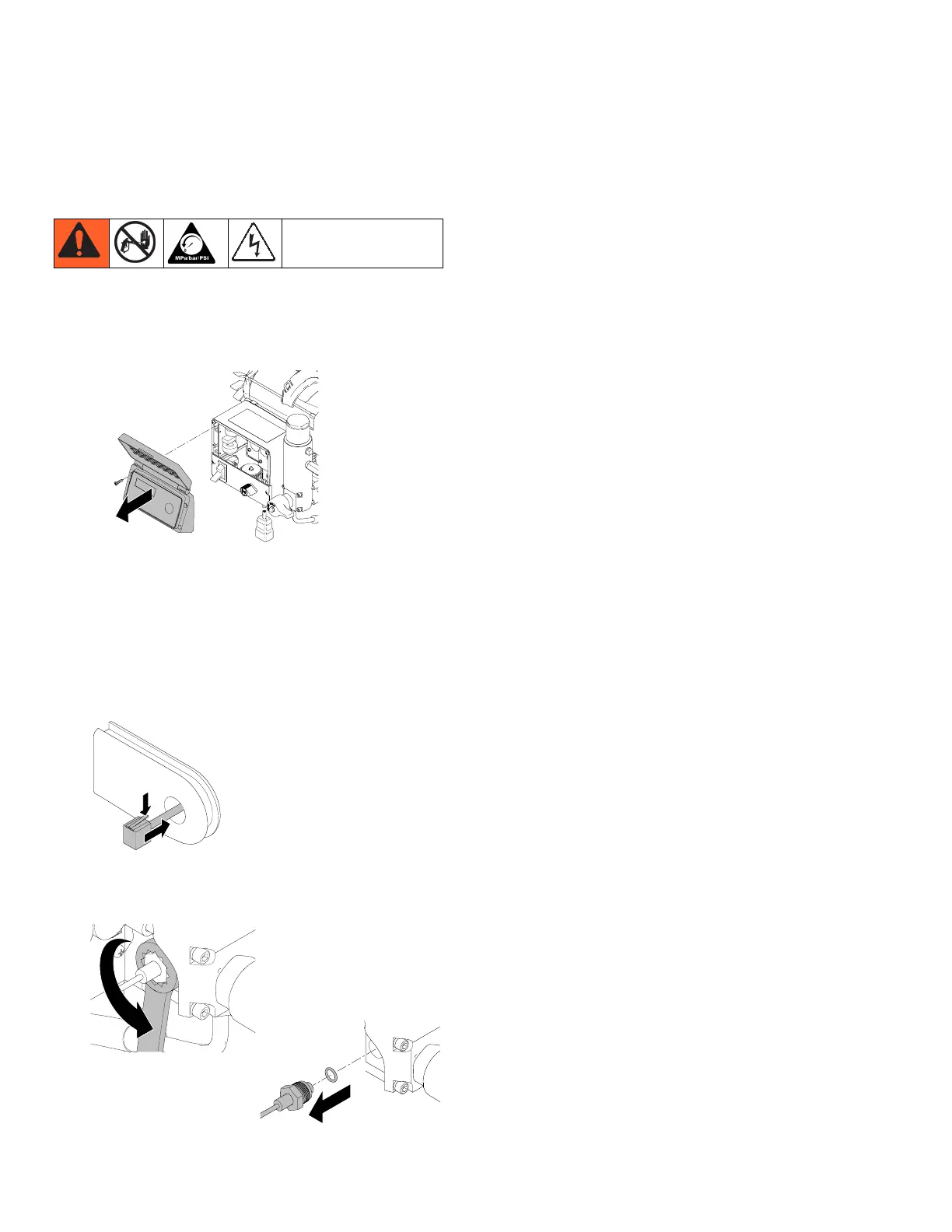
Pressure Control Transducer
24 3A2244A
Pressure Control Transducer
Removal
1. Turn power OFF. Wait 5 minutes for power to dissi-
pate. Perform Pressure Relief Procedure, page 9.
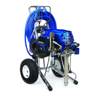
2. Remove display.
3. Remove control panel.
4. Disconnect transducer from motor control board.
5. Remove two screws and allow control panel to hang
down.
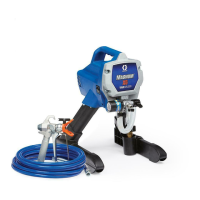
6. Press tab on transducer connector and pull trans-
ducer wire through grommet.
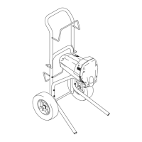
7. Route transducer wire through 3/4 in. box. end
wrench and remove transducer and o-ring from
valve block.
Installation
1. Install transducer and o-ring in valve block. Torque
to 47 - 61 N•m (35 - 45 ft-lb).
2. Press tab on transducer connector and push trans-
ducer wire through grommet.
3. Install control box. Torque screws to 3.4 - 3.9 N•m
(30 - 35 in-lb).
4. Connect transducer connector to motor control
board.
5. Connect display connector to motor control board.
6. Install cover with four screws.
ti18387a
ti18410a
ti18409a
ti18411a