Repair
Transformer Primary Check
See Electrical Sche matics, page 91.
1. Check wires and transformer:
a. See Shutdown, page 44.
b. Shut off CB05.
c. Use an ohmm eter to test for continuity
between terminals 2 and 4 of CB05. If there
is no continuity, check transformer.
2. Check transformer:
a. See Shutdown, page 4 4.
b. Remove lower shroud.
c. Locate the two smaller (10 AWG) wires,
labeled 1 and 2, coming out of transformer.
Trace these wires back to terminal blocks
TB15 and TB16.
d. Use an ohmmeter to test for continuity
between two wires; there should be
continuity.
Transformer Secondary Check
See Electrical Sche matics, page 91.
1. Check wires and transformer:
a. Disconnect 7 pin green connector from TCM.
b. Use a n ohmmeter to test for continuity
between terminals 6 and 7 on the TCM 7 pin
green connector. There s hould be continuity.
If there i s no continuity, check transformer.
c. Reconnect 7 pin green connector to TCM
2. Check transformer:
a. Remove lower shroud.
b. Locate the two larger (6 AWG) wires,
labeled 3 and 4, coming out of transformer.
Trace the se wire s back to TB1 7 and TB1 8.
Open circu it breaker CB01 to turn the col or
indica tor on th e ci rcu it b reak er GRE E N. Us e
an ohmmeter to test for continuity between
two transformer wires in terminal blocks
TB17andTB18;thereshouldbecontinuity.
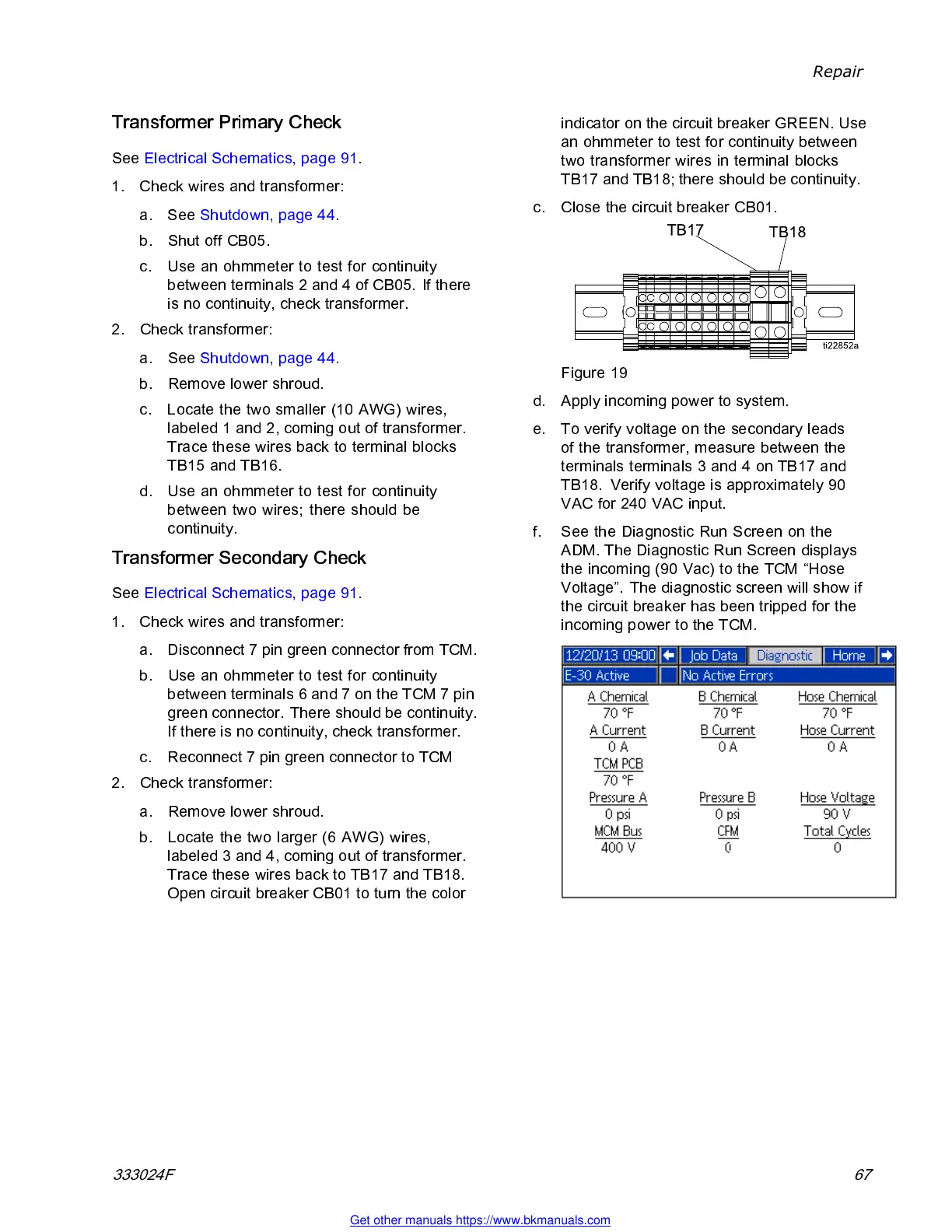
c. Clos e the circ ui t b reak er CB01.
Figure 19
d. Apply incoming power to system.
e. To verify voltage on the secondary leads
of the transformer, measure between the
terminals terminals 3 and 4 on TB17 and
TB18. Verify voltage is approximately 90
VAC for 240 VAC input.
f. SeetheDiagnosticRunScreenonthe
ADM. The Diagnostic Run Screen displays
the incoming (90 Vac) to the TCM “Hose
Voltage”. The diagnostic screen will show if
the circuit breaker has been tripped for the
incoming power to the TCM.
333024F 67
Get other manuals https://www.bkmanuals.com