Setup
22 309812D
8. Connect heated hose
See 309572 for detailed instructions for Graco
heated hoses.
CAUTION
The fluid temperature sensor (FTS) and whip hose
must be used with heated hose, see page 21. Hose
length, including whip hose, must be 60 ft (18.3 m)
minimum.
a. Turn main power OFF .
b. Assemble heated hose sections, FTS,
and whip hose.
c. Connect A and B hoses to A and B out-
lets on Reactor fluid manifold (FM).
Hoses are color coded: red for compo-
nent A (ISO), blue for component B
(RES). Fittings are sized to prevent con-
nection errors.
FM
A
B
TI2726A
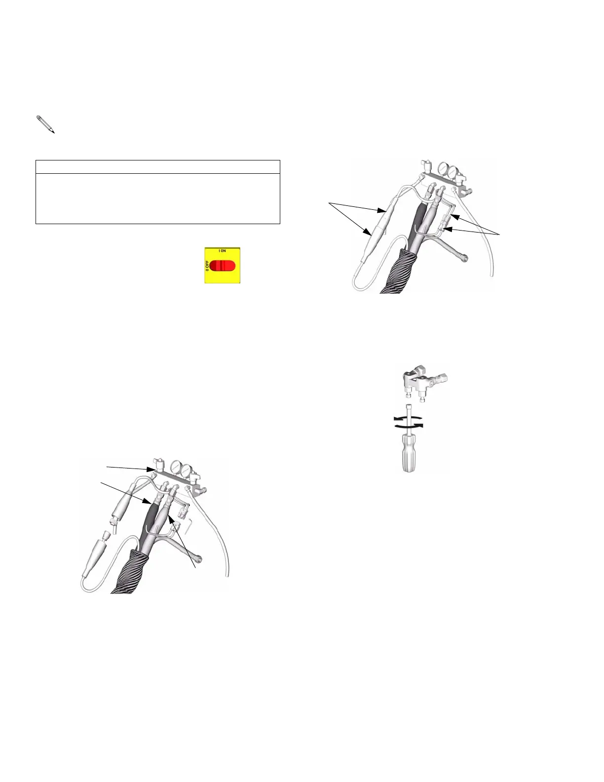
d. Connect cables (Y). Connect electrical
connectors (V). Secure with plastic ties.
Be sure cables have slack when hose
bends. Wrap cable and electrical con-
nections with electrical tape.
9. Close gun fluid manifold
valves A and B
TI2727A
V
Y
TI2411A
 Loading...


