Setup
309812D 23
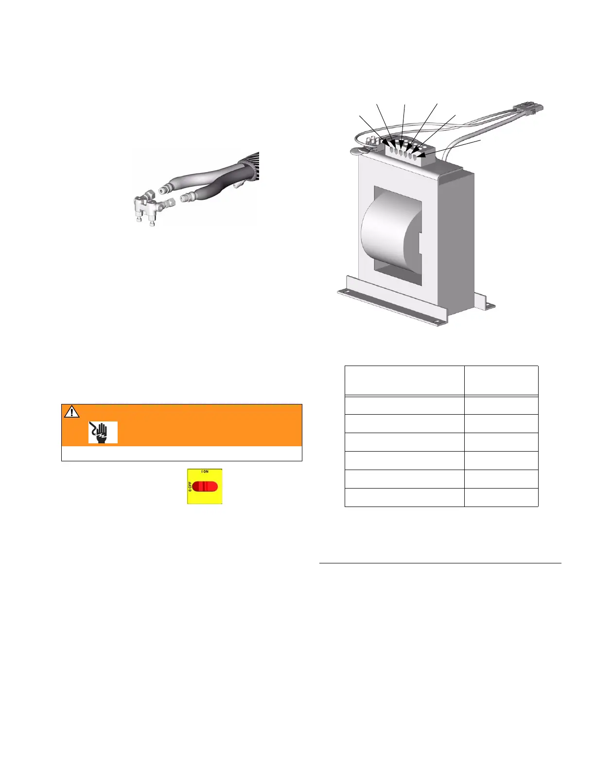
Turn main power switch OFF . Transformer tap
wire connections vary depending on length of heated
hose. See F
IG. 6. Verify that tap wire connections are
correct.
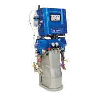
10. Connect whip hose to
gun fluid manifold
Do not connect manifold to gun yet.
11. Pressure check hose
See hose manual. Pressure check for leaks. If
no leaks, fully wrap hose and electrical connec-
tions with tape to protect from damage.
12. Set transformer wire
taps
WARNING
Read warnings, page 8.
TI2417A
FIG. 6: Transformer Wire Taps
* Length includes heated fluid hose and whip hose.
Hose Length* ft (m) Tap Terminal
Label (ft)
60-85 (18.3-25.9) 50
110-135 (33.5-41.2) 100
160-185 (48.8-56.4) 150
210-235 (64.1-71.7) 200
260-285 (79.3-86.9) 250
310 (94.6) 300
TI3470a
50 ft
100 ft 150 ft 200 ft
250 ft
300 ft
 Loading...