Temperature Control Diagnostic Codes
12 309574L
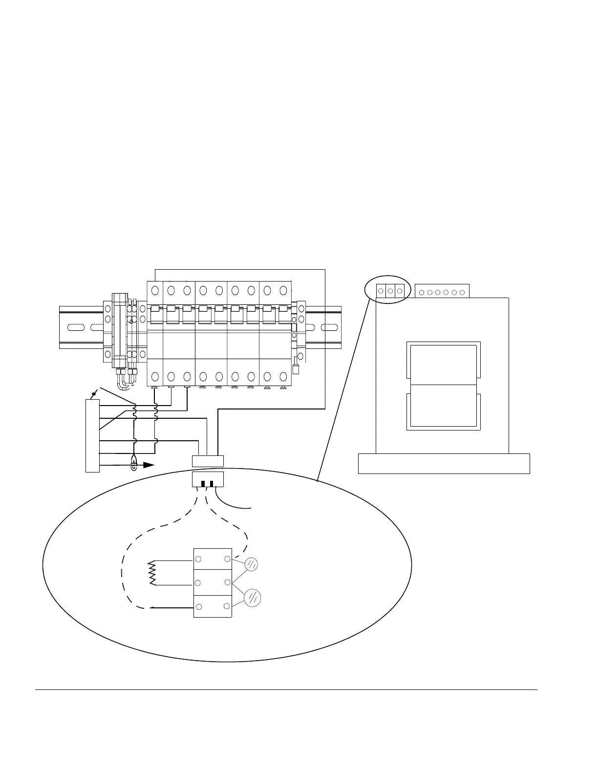
3. With the main power off, the hose plugged in, and
wire harness from the connector J13 still removed
from the temperature control board:
a. Check for continuity between Pin 1 on the J13
harness, and the bottom of the left 20-amp hose
breaker. See F
IG. 2.
b. Check for continuity between Pin 2 on the J13
harness, and one of the leads of the black
In-rush limiter located on the upper left hand
side the transformer.
c. Check for continuity between Pin 3 on the J13
harness, and the bottom of the right 20-amp
hose breaker.
d. Check for continuity between Pin 4 on the J13
harness, and the opposite lead of the black
In-rush limiter from step b, located on the upper
left hand side the transformer.
e. Check for continuity between Pin 5 on the J13
harness, and the bottom of the 50-amp hose
breaker.
F
IG. 2
1
2
3
4
5
6
1 2 3
J13
Tra n s fo r me r
456 78
9
50 FT
100 FT
150 FT
200 FT
250 FT
300 FT
Front of
Black
Red
Transformer
1 2 3
Back of
Transformer
3-Pin Connector
Wire No. 3
(from back of transformer)
Wire No. 2 (already connected)
Terminal Block
Wire No. 2 (from
back of transformer)
Wire No. 1 (from
back of transformer)
Wire No. 1 (already connected)
To
Hose
50
A
Hose
A
BPump
Wire harness
15B378