Installation
3A5999E 9
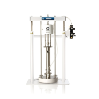
Stand and Mounting
For pumps that are provided with a stand, the pump
must be mounted to the stand before securing the pump
to the mounting surface. Ensure that the pump is
securely mounted to the stand.
Stand sizes:
1. Ensure that the mounting surface is level and can
support the weight of the pump, lines, and
accessories, as well as the stress caused during
operation.
2.
Mount the pump and stand assembly on a level
surface and secure the assembly to the mounting
surface. See Pump Dimensions, pages 16–28, for
dimensions of the mounting holes for your pump.
NOTE: For ease of operation and service, mount
the pump so the air valve cover, air inlet, and fluid
inlet and outlet ports are easily accessible.
Air Line
1. Install the air line accessories as shown in FIG. 2.
Verify that the air line supplying the accessories is
grounded.
a. Install an air regulator (B) and air pressure
gauge (T) to control the fluid pressure.
Reducing the supplied air pressure will reduce
the pump’s fluid outlet pressure.
b. Locate one bleed-type master air valve (C)
close to the pump and use it to relieve trapped
air. Locate the other master air valve (A)
upstream from all air line accessories and use it
to isolate them during cleaning and repair.
c. The air line filter (R) removes harmful dirt and
moisture from the compressed air supply.
2. Install a conductive, grounded, flexible air line (D)
between the accessories and the 1/2 npt(f) pump air
inlet (F). Use a minimum 3/8 in. (9.5 mm) ID air line.
If necessary, install an air line coupler (E) between
the air line (D) and the pump air inlet (F), and tighten
until snug.
3-A Pumps: If a leak sensor kit was supplied with
your 3-A pump, see the provided kit manual for
information on installing the sensors. See Related
Manuals, page 2.
The pump may be very heavy (see Technical
Specifications for specific weights). If the pump must
be moved, follow the Pressure Relief Procedure on
page 13 and have two people lift the pump by
grasping the outlet manifold securely, or use
appropriate lifting equipment. Never have one person
move or lift the pump.
Pump Type Part No. Base Dimensions
Vertical
4150 flapper
25P104 18.0 in x 23.0 in
(45.72 cm x 58.42 cm)
Horizontal
flapper
25N991 15.75 in x 14.0 in
(40.00 cm x 35.56 cm)
Rotatable 24L978 17.3 in. x 23.8 in.
(43.94 cm x 60.45 cm)
1040 25P103 10.5 in x 12.0in.
(26.67 cm x 30.48 cm)
A bleed-type master air valve (C) is required in the
system to relieve air trapped between this valve and the
pump. Trapped air can cause the pump to cycle
unexpectedly, which could result in serious injury
including splashing in the eyes or on the skin. See FIG.
2.
 Loading...