Controls and C onn ections
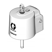
Control Panel
(Electro-Pneumatic)
Part No. 25D009
When supplied with 110–240 VAC power and a
continuous supply of air, the control panel can control
the STU functions for automatic, manual, or batch
unloading of totes.
This panel is UL508A certified and requires using
only Listed or Recognized components. Replacing
parts with genuine Graco parts is important to
maintain this certification. See the parts manual for
replacement part numbers.
Ref. Symbol
Description
CA
———
Touch screen display: Operator interface for control of the STU.
CB
———
AC power switch: Controls whether power is applied to the control panel.
CC
———
Emergency stop button: Press to cease STU operation immediately. This should not be
used as a means to shut off the system during normal operation.
CD
———
Position sensor: Access hole and sealed strain relief for the laser position sensor.
CE
———
Control Panel Supply Ball Valve: Connect a clean, dry, air supply to this valve for the
control valve. This valve will supply air to control valve pilots, air assist, and the inflatable
seal.
NOTE: It is recommended that the Control Panel Supply be separate from the Pump
Supply to avoid the high air consumption of pumps from starving the control pilots. Use
only clean dry air.
CF
———
Pump Air Supply Ball Valve: Connect a clean, dry, air supply to this valve for the pumps.
See specific pump instruction manual for minimum and maximum pressure and flow
requirements. Use only clean dry air.
CG Seal Inflation Port: Route hose through the hose block on the side of the frameand
through holes in the support plate to the inflation tube (A1) of the inflatableseal.Usethe
provided 172 inch hose
CH Air Assist Port: Route hose through the hose block on the side of the frame and through
holes in the support plate to the check valve (B1) in the center of the ram plate. Use the
provided 172 inch hose.
2
2
3A5416C
 Loading...