15309710
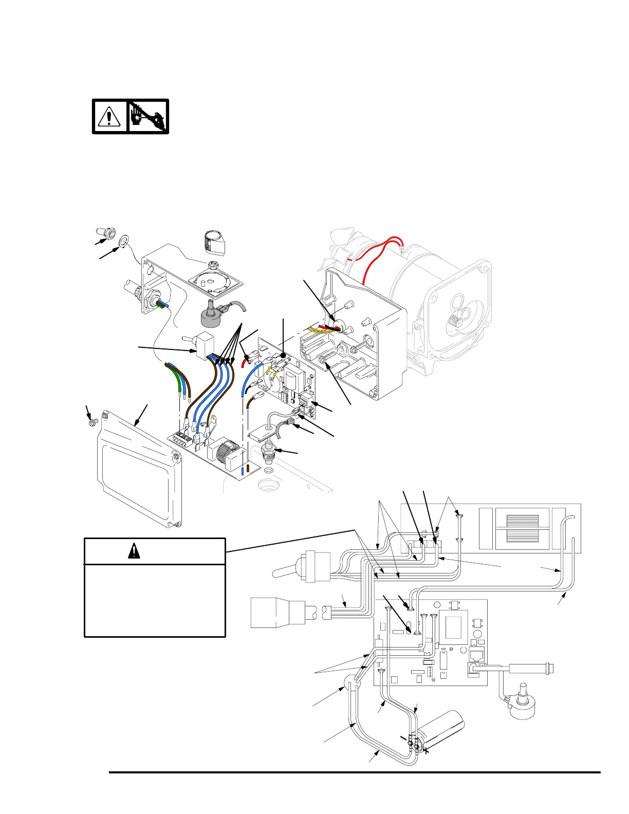
On/Off Switch Replacement
240 Vac 234175, 234177, 234179, 246993
Removal
1.
Relieve pressure; page 4.
2. Fig. 8. Remove pressure control cover (39).
3. Disconnect four wires (A) at ON/OFF switch (23).
4. Remove toggle boot (25) and locking ring (24).
Remove ON/OFF switch (23).
Installation
1. Install new ON/OFF switch (23). Install locking ring
(24) and toggle boot (25).
2. Connect four wires (A) to ON/OFF switch.
3. Install pressure control cover (39).
ti0055b
Fig. 8
39
A
23
36
52
E
D
25
24
C
35
37
18
L1L2
TP1 TP2
Pressure
Transducer
ON/OFF
Switch
Power
Plug
Potentiometer
from Motor
Filter Board
Red (+)
Wiring Diagram
Heat from inductor coil of filter board
may destroy wire insulation that
comes in contact with it. Exposed
wires could cause shorts and com-
ponent damage. Bundle and tie all
loose wires so none lay in contact
with inductor coil of filter board.
Caution
Yellow
Brown
TI0058
Capacitor
Blue
Black (–)
BrownBlue
Green/Yellow
22
Black/White (–)
Red/White (+)