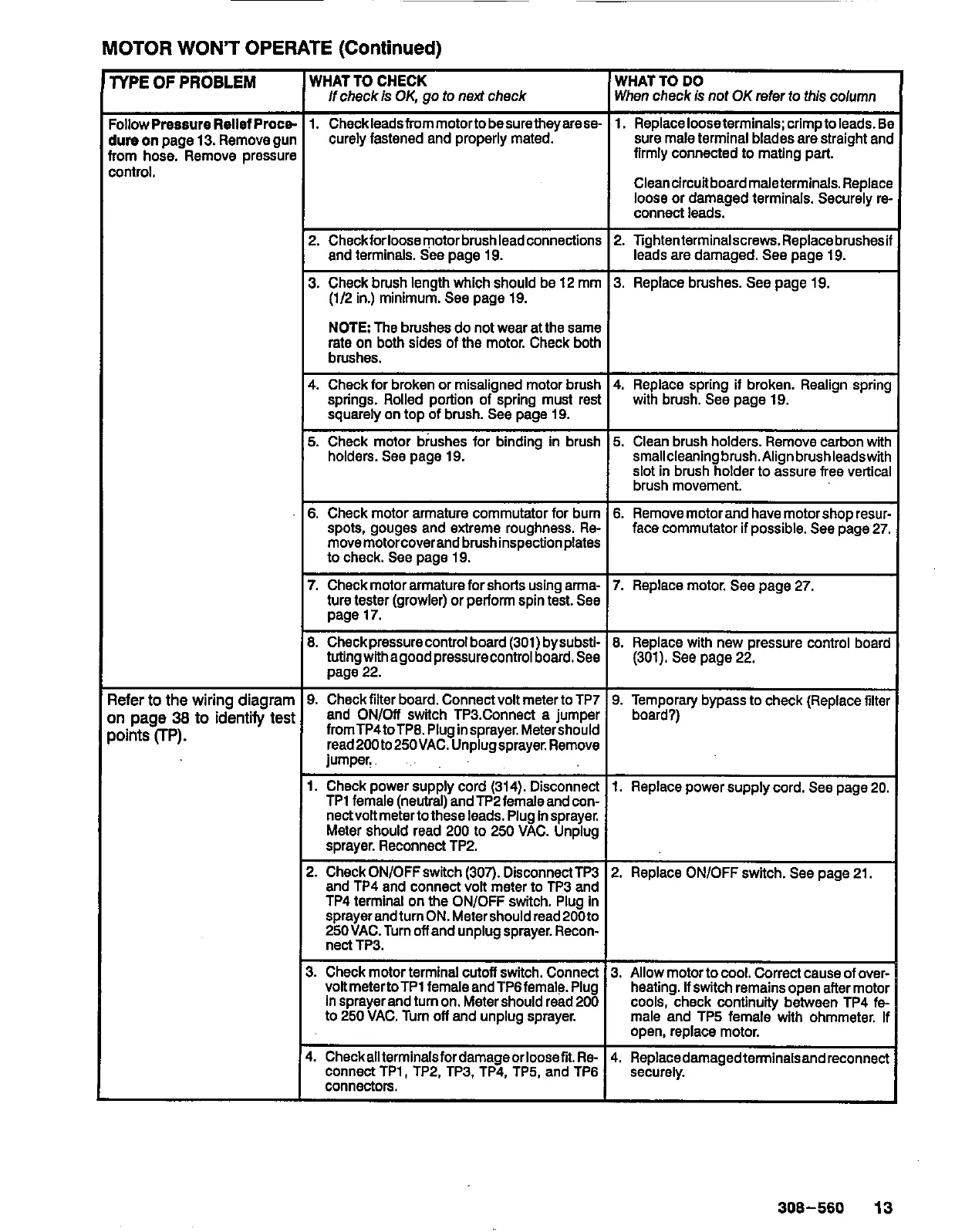
~
MOTOR
WON'T
OPERATE
(Continued)
YPE
OF
PROBLEM
Ollow
Pressure
Rellef
Proce
lure
on
page
13.
Remove gur
'om hose. Remove pressurf
ontrol.
lefer
to
the
wiring diagram
n
page
38
to
identify
tesi
oints
(TP).
WHAT TO CHECK
WHAT TO
DO
lfcheck
is
OK,
go
to
next
check When check is
not
OK
refer
to
this column
1.
Checkleadsfrommotortobesuretheyarese-
firmly connected
to
mating part.
sure male terminal blades are straight and
curely fastened and properly mated.
1.
Replacelooseterminals;crimptoleads.Be
Cleancircuitboardmaleterminals.Replace
loose
or damaged terminals. Securely re-
connect leads.
2.
Checkforloosemotorbrushleadconnections
3. Replace brushes. See page 19.
3. Check brush length which should be 12 mm
2.
lightenterminalscrews.Replacebrushesif
and terminals.
See
page 19.
(1/2 in.) minimum. See page 19.
leads are damaged. See page 19.
NOTE
The brushes do not wear at the same
rate on both sides of the motor. Check both
brushes.
4. Check for broken or misaligned motor brush
springs. Rolled portion of spring must re&
squarely on top of brush. See page 19.
5.
Check motor brushes for binding in brush
holders. See page 19.
6.
Check motor armature commutator for bum
spots, gouges and extreme roughness.
Re-
movemotorcoverandbrushinspectionplates
to
check.
See
page 19.
7.
Checkmotorarmatureforshorts using arma-
ture tester (growler) or perform spin test.
See
page 17.
8.
Checkpressurecontrolboard (301) bysubsti-
tutingwithagoodpressurecontrol
board.See
page
22.
9.
Check filter board. Connect volt meter to TP7
and ON/Off switch TP3.Connect a iumDer
fromTP4toTPB.Pluginsprayer.Mete&hchd
read200to250VAC.Unplugsprayer.Remove
jumper.
..
1.
Check power supply cord (314). Disconnect
TPt female (neutral) andTP2femaleandcon-
nectvolt metertothese leads. Plug Insprayer.
sprayer. Reconnect TP2.
Meter should read 200
to
250
VAC. Unplug
2.
CheckON/OFFswitch (307). DisconnectTP3
and TP4 and connect volt meter to TP3 and
TP4 terminal on the ONlOFF switch. Plug in
sprayerandturnON.Metershouldread200to
25OVAC. Turn
off
and unplug sprayer. Recon-
nect TP3.
~~ ~ ~~~~ ~~~
4.
Replace spring
if
broken. Realign spring
with brush. See page 19.
5.
Clean brush holders. Remove carbon with
smallcleaninabrush.Alianbrushleadswith
slot
in
brushholder to &sure free vertical
brush movement.
I
6.
Removemotorand have motorshop resur-
face commutator if possible. See page 27.
(301). See page
22.
9. Temporary bypass
to
check (Replace filter
board?)
3.
Check motor terminal
cutoff
switch. Connect
to
250
VAC. Turn
off
and unplug sprayer.
heating.
If
switch remains open after motor
voRmetertoTP1 femaleandTP6female. Plug
3. Allow motor
to
cool. Correct cause of over-
Insprayerand turnon. Metershould read200
cools, check continuity between TP4 fe-
male and TP5 female with ohmmeter.
If
open, replace motor.
4.
Checkallterminalsfordamageorloosefit.Re-
4.
Replacedamagedterminalsandreconnect
connect TP1, TP2. TP3. TP4, TP5, and TP6
securely.
connectors.
I
I
308-560
13