123456
4
3
2
1
123456
4
3
2
1
123456
4
3
2
1
4
3
2
1
Appendix A: More about Class 2/PELV Wiring
This appendix explains the Class 2/PELV wiring used to carry communications between GRAFIK
Eye Control Units and Wallstations.
Lutron requires that you connect (daisy-chain) all GRAFIK Eye 3000 Series Control Units and
Wallstations with two twisted pair for operation. If shielded wire is used, the drain wires must be
connected to each other or to Terminal D, if present. Drain wires should not be connected to
Earth/Ground.
■ One pair is for the low-voltage power wiring that enables each GRAFIK Eye Control Unit to
supply power to up to three Wallstations. Connect this twisted pair to terminals 1
(COMMON) and 2 (12VDC). Terminate the 12VDC power to ensure that each Control Unit
powers
no more than three
Wallstations.
■ The second pair is for a data link (up to 2000 ft. or 450 m long) that enables Wallstations to
communicate with GRAFIK Eye Control Units. Connect this twisted pair to terminals 3 (MUX)
and 4 (MUX) of every Control Unit and Wallstation.
Each twisted pair in the Class 2/PELV wiring link should consist of two #18 AWG (1.0 mm
2
)
stranded conductors.
■ Lutron offers a one-cable (non-plenum), low-voltage solution. Please ask for
P/N GRX-CBL-346S.
Recommended unshielded cables:
■ For non-plenum installations, use (2) Belden 9470, (1) Belden 9156, or (2) Liberty 181P/
2C-EX-GRN, or equivalent.
■ For plenum installations, use (2) Belden 82740, or equivalent.
Wallstation circuits are classified as Class 2 circuits (U.S.A) and PELV circuits (IEC). Unless otherwise specified, the voltages do not exceed 24VAC or 15VDC. As
Class 2 circuits, they comply with the requirements of NFPA 70, National Electrical Code (NEC). As PELV circuits, they comply with the requirements of IEC 60364-4-
41, VDE 0100 Part 410, BS7671:1992 and other equivalent standards. When installing and wiring to these Wallstations, follow all applicable national and/or local
wiring regulations. External circuits connected to input, output, RS232, DMX512, and other communication terminals of Wallstations, must be supplied from a Listed
Class 2 source or comply with the requirements for PELV circuits as applicable in your country.
The GRAFIK Eye 3000 Series Control Unit Class 2/PELV circuit is 12VDC.
Page 12
EACH TERMINAL CAN ACCEPT UP TO
2 #18 AWG (1.0 mm
2
) WIRES
CLASS 2/PELV
POWER WIRING:
2: 12VDC
1: COMMON
ACCESSORY
CONTROL 1
ACCESSORY
CONTROL 2
ACCESSORY
CONTROL 3
GRAFIK Eye
3000 SERIES
CONTROL UNIT
DATA LINK:
4: MUX
3: MUX
What is PELV?
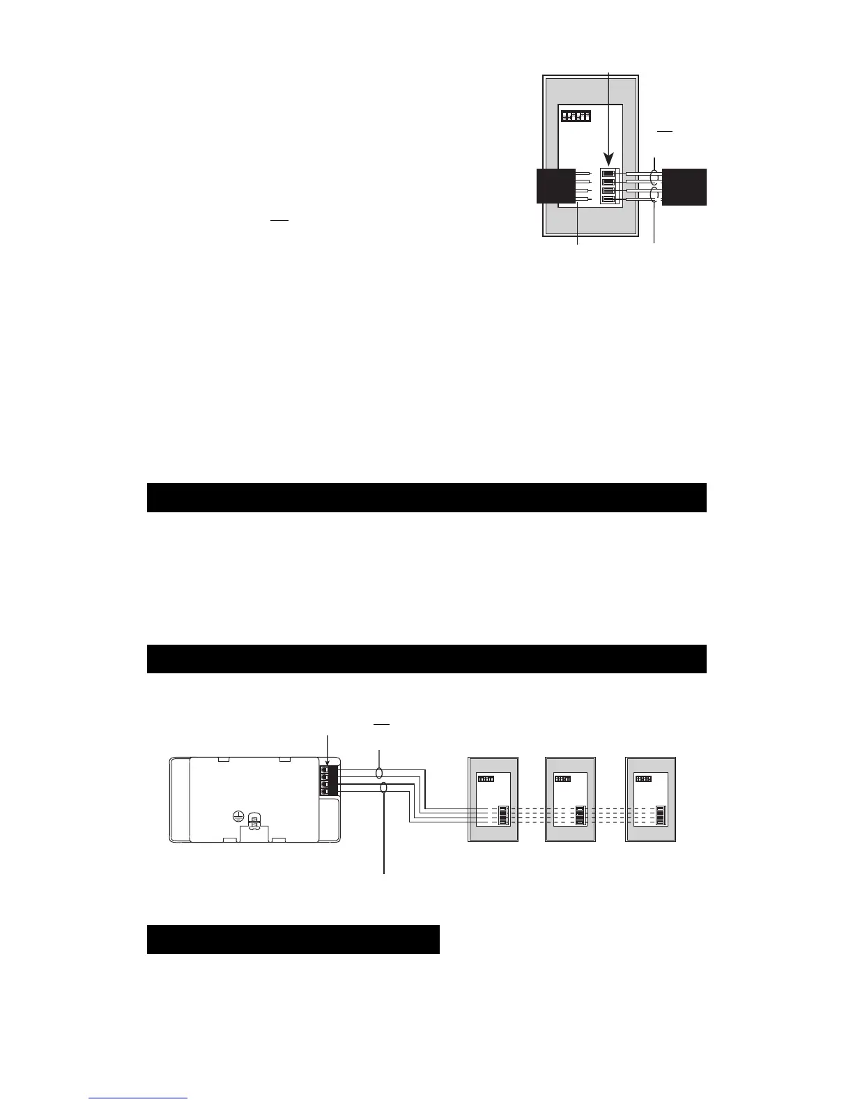
Small project: A Control Unit with up to three Wallstations
EACH TERMINAL CAN ACCEPT UP TO
2 #18 AWG (1.0 mm
2
) WIRES
CLASS 2/PELV
POWER WIRING:
2: 12VDC
1: COMMON
2 TWISTED PAIRS
#18 AWG (1.0 mm
2
)
DATA LINK:
4: MUX
3: MUX
In countries that abide by the IEC regulations, PELV is commonly referred to as Protective Extra-Low Voltage. A PELV circuit is an earthed
circuit in which the voltage cannot exceed 50VAC or 120V ripple-free DC. The power source must be supplied by a safety isolating transformer
or equivalent.
IMPORTANT WIRING NOTE!
Proper separation is required between the Line Voltage/Mains cables and PELV cables. Use certified cable for all Line Voltage/Mains cables
and PELV cables. Cable bearing HAR or national certification marks are acceptable, provided it covers all applicable wiring regulations for
fixed installations. See Important Wiring Note on page 3.
Each Control Unit can power up to three Wallstations. If you need to power more than three Wallstations from one Control Unit, install an
external 12VDC power supply as described later in this section.
Maximum of 1000 ft. (300 m) between the GRAFIK Eye Control Unit and the
third Wallstation. For longer distances, use an external Class 2/PELV rated
12VDC power supply (see page 13).
IMPORTANT WIRING NOTES!
1. Daisy-chain the terminal 1, terminal 2, terminal 3, and terminal 4 connections to all Control Units and Wallstations. The Control Unit
has
its own
power supply.
2. Each Control Unit can power up to three Wallstations. If you need to power more than three Wallstations from one Control Unit, install an
external 12VDC power supply as described later in this section.
3. Lutron recommends that all connections be made in the unit wallbox. Remote connection must be in a switchbox or junction box with a
maximum wire length of 8 ft. (2.5m) from the link to the connected unit.
Note: Do not allow Class 2/PELV wires to contact line/mains wires. Refer to Class 2/PELV wiring on page 4.

 Loading...