Class 2/PELV Wiring
M S
FADE TEMPORARY
MASTER
ZONES
ZONE 5 ZONE 6ZONE 3 ZONE 4ZONE 1 ZONE 2
Scene 1
button
OFF
Zone intensity raise and lower
buttons
Scene 1 LED
Page 4
1
2
3
4
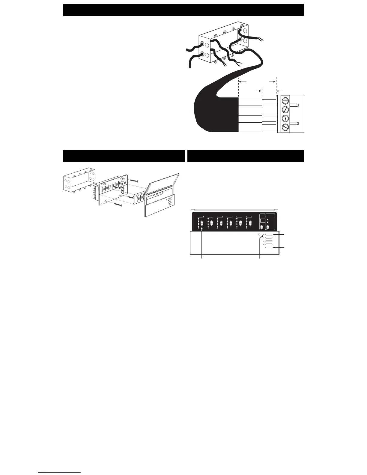
LINE VOLTAGE/MAINS CABLE
CLASS 2/PELV
TERMINAL
CLASS 2/PELV CABLE
1.0 in. (25 mm)
3/8 in.
(9.5 mm)
LINE VOLTAGE/MAINS CABLE
1. Mount as shown using the four screws provided. (When mounted in
the wallbox, the Class 2/PELV cable and terminal block should
remain separated from the line voltage/mains cables.)
2. Reattach the faceplate to the Control Unit by pushing inward at each
corner.
Testing: Do the lights work?
IMPORTANT WIRING NOTES!
Review Appendix A BEFORE wiring!
■ Wallstations must be installed by a qualified electrician.
■ Wallstations use Class 2 or PELV wiring methods as applicable in your
locale.
— Using Class 2 wiring methods: Wallstations must be connected in
accordance with the 1996 National Electrical Code, Article 725-54(a),
(1) Exception No. 3 or the Canadian 1994 CE Code Handbook, Rule
16-212, Subrule (4). Check with your local electrical inspector to
comply with local codes and wiring practices.
— Using PELV wiring methods: Wallstations that are connected to
terminals 1—4 must always meet the requirements of DIN VDE 0100
Part 410 and IEC 60364-4-41 for PELV circuits. See “What is PELV?”
in Appendix A.
■ Wallstations must be mounted in a wallbox. Please refer to instruction sheet
included with each Wallstation to determine wallbox requirements.
■ Note that the NTGRX-1S can use line voltage/mains branch circuit wiring.
Refer to the installation instructions packaged with the Wallstation.
Connect Class 2/PELV wiring
only if your project has Wallstations
and/or more than one Control Unit
.
Use recommended cable as specified in Appendix A: More About
Class 2/PELV Wiring.
Wiring Note
■ Use the rearmost knockouts when pulling wires into the wallbox.
This will provide the most clearance when mounting the Control
Unit.
1. Strip 1 in. (25 mm) of insulation from the Class 2/PELV cable.
2. Strip 3/8 in. (8 mm) of insulation from each wire.
3. Connect the Class2/PELV wires to the Class 2/PELV
terminal block. Make sure no bare wire is exposed after
making connections. The recommended installation torque is
3.5 in.
●
lbs. (0.4 N
●
m) for Class 2/PELV connections.
4. The Class 2/PELV cable and terminal block should be separated
from line voltage/mains cables by at least 1/4 in. (7 mm).
Mounting
1. Restore Power.
2. Press Scene 1 button on front of the GRAFIK Eye Control
Unit. The Scene 1 LED will light.
3. Press zone
55
55
5 or
66
66
6 to raise or lower the light levels. Make
sure that the Control Unit is dimming all connected loads. Refer
to Appendix G: Troubleshooting, or call Lutron.
STEP 2: Installing Wallstations
Examples of Wallstations
NTGRX-2B-SL Entrance/Special Function Control
NTGRX-4S Scene Selection Control with Raise/
Lower
NTGRX-4S-IR Scene Selection Control/Infrared
Receiver
NTGRX-4B Scene Selection Control
NTGRX-4M Master Control
NTGRX-4PS Partition Control
GRX-CIR* Infrared Ceiling Receiver
GRX-4S-DW* Architrave
TM
Door Jamb Control
GRX-AV* Interface Control
GRX-RS232* RS-232 Interface Control
GRX-PRG* Personal Computer Interface
GRX-IT/GRX-8IT Infrared Handheld Transmitter
(see Appendix C)
EGRX-4S* European Style 4S Control
EGRX-4S-IR* European Style 4S Control/Infrared
Receiver
. . . and more!

 Loading...