Material No. 1 447 263
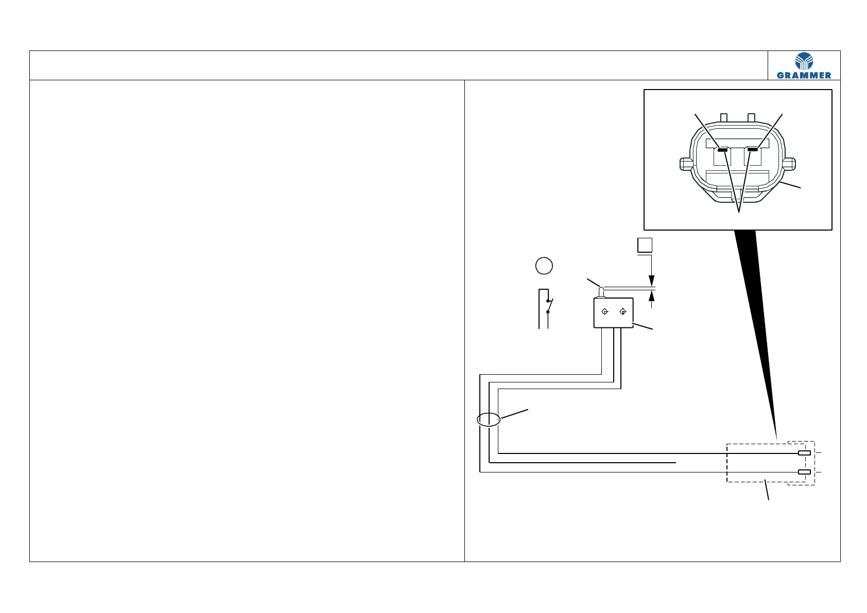
Seat switch and pin assignment with
circuit diagram
(1) Seat switch cable harness
(3) On-board power supply connector
(9) Seat switch
(13) Seat switch lifter
(14) Assignment as normally open
contact (Z)
(Pin: P1 and P2)
(X) Line end. The line is not laid up to
the on-board power supply
connector (3).
(Z) The seat switch (9) is closed when
the seat is compressed.
The vehicle can be put into
operation.
Note:
Distance (A) between the rest position
and switching point of the seat switch
lifter (13) = 1,2 mm.