Page 16
Fire Bowls and Inserts Premium Line
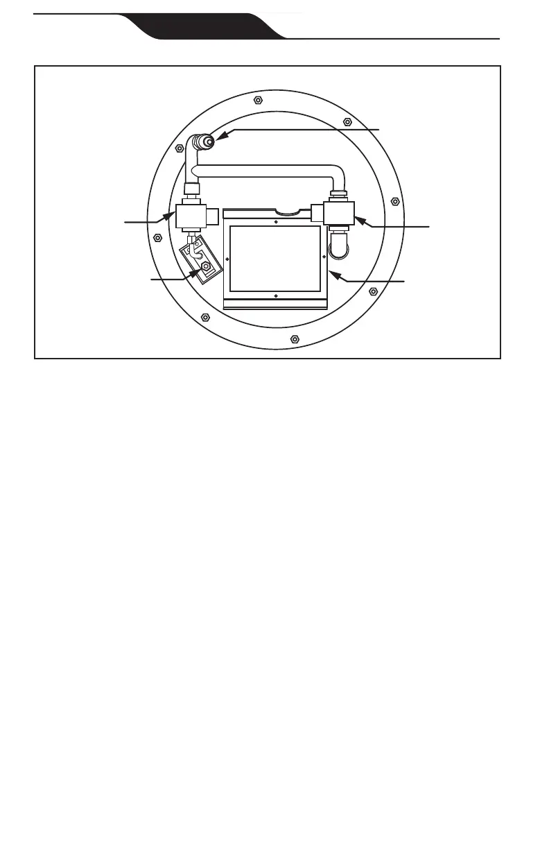
Automated Operation
IGNITOR
PILOT SOLENOID
ENCLOSURE WITH
IGNITION MODULE
MAIN
SOLENOID
GAS INLET
Figure 10. Bottom-side of Burner Assembly
4.2 Burner Adjustment
Note: Each burner should have a ame height of approximately 12″ – 15″
from the top of the bowl. If the pressure to the burner is too low, it
will create an unstable pilot, resulting in possible On/Off cycling.
1. The height of the ame can be adjusted at each burner by opening or
closing the ½″ gas valve or keyed valve located on each column as
shown in Figure 7.
Each burner should be adjusted as required so that the ame size at
each bowl is similar in appearance to each other.
2. After all burners have been adjusted, make sure that the burner
assembly is repositioned so that it is sitting level in each bowl.
3. Install decorative rock or glass on top of the “burner support” and
burner assembly. Larger lava rock is recommended (2″ - 4″ in size). It
will work better than smaller rock. Make sure that all rock is clear of the
pilot area and hood area. Pilot hood area needs to remain clear of rock
for proper ventilation.