45
INSTALLATION, CONNECTIONS, AND ADJUSTMENTS
• at least 500 mm of free space between the appliance and the rear wall;
• at least 50 mm of free space between appliance side and side wall or other appliance.
Moreover, check that:
• the electric absorption of the appliance is lower than that supplied by the electric company;
• the steam and water pressure available (for appliances provided with this type of heating) are within the accepted values.
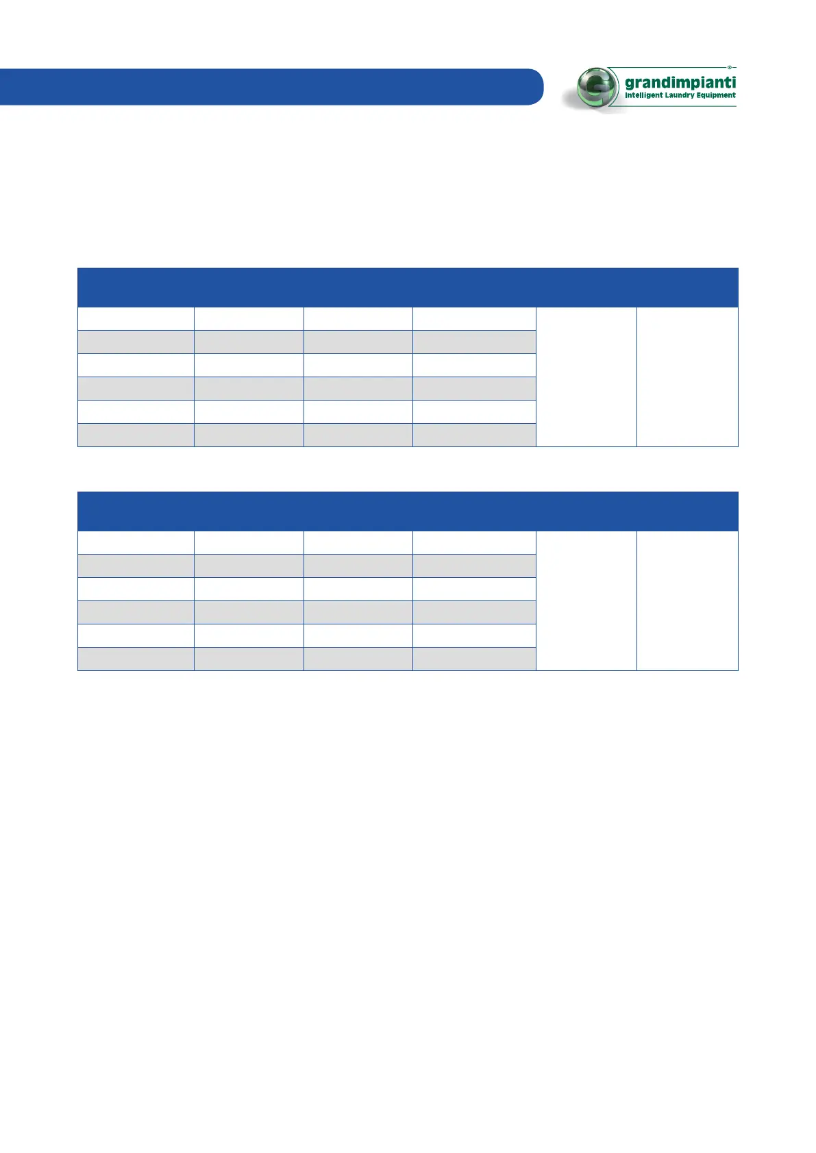
Below we indicate the accepted values for models GWM/ GWN:
Model
Max. floor static
load (kN)
Dynamic floor load
(kN)
Dynamic load
frequency (Hz)
Max. water
pressure (KPa)
Max. steam
pressure (KPa)
kg 8 1.9 1.6 ± 2.4 13.7
800 600
kg 11 2.2 1.9 ± 4.0 12.7
kg 14 2.7 2.2 ± 5.1 12.7
kg 18 3.4 2.7 ± 3.6 8.2
Kg 24 3.9 3 ± 4.8 8.2
Kg 28 4.2 3.22 ± 5.6 8.2
Allowed values for the GWH models:
Model
Max. floor static
load (kN)
Dynamic floor load
(kN)
Dynamic load
frequency (Hz)
Max. water
pressure (KPa)
Max. steam
pressure (KPa)
kg 8 2.3 1.9 ± 0.5 19.4
800 600
kg 11 2.6 2.2 ± 0.5 17.9
kg 14 3.2 2.7 ± 0.5 17.9
kg 18 4.9 4.0 ± 0.7 16.3
Kg 24 5.3 4.6 ± 1.1 16.3
Kg 28 5.8 5.0 ± 1.1 15.25
Prepare some wall taps at a distance that must not exceed the length of the supplied pipes.
 Loading...