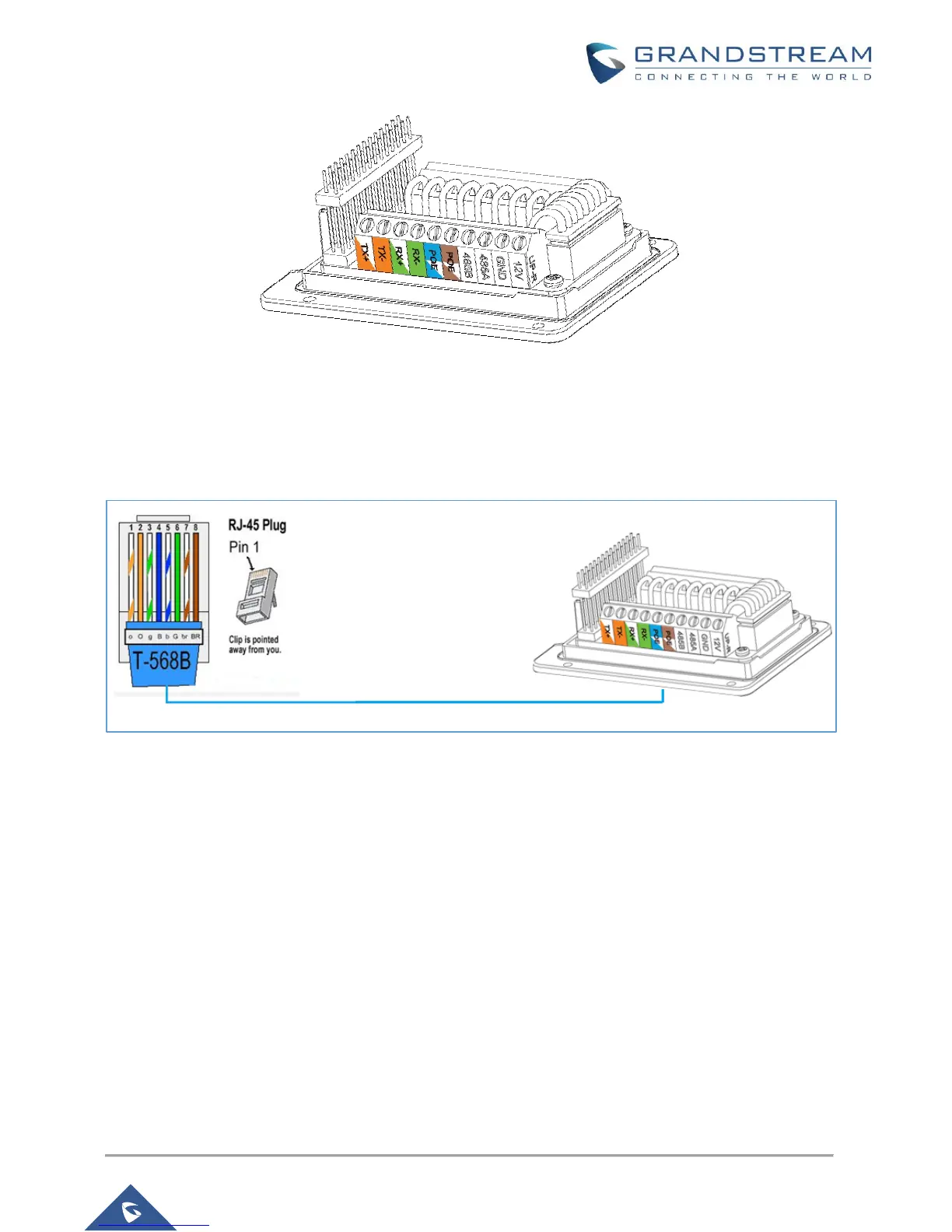
Figure 2: GDS3710 Back Cover 1
In order to power the GDS3710 using PSU, please follow steps below:
1- Use a multimeter to detect the polarity of your Power Supply, then connect the Back Cover GND
to negative pole and 12V to positive pole of the PSU.
2- Cut into the plastic sheath of your RJ45 cable, then unwind and pair the colors like shown below
Figure 3: Connection Example 2
3- Connect wires OrangeWhite/Orange and GreenWhite/Green of the RJ45 to its associate on the
GDS3710
Note: The Blue and Brown PINs are used for PoE, therefore when using PSU we only need to connect the
data wires, power will be provided to the GDS3710 trough (12V,GND).
Alarm In and Alarm Out PINs
The GDS3710 have two Alarm input entries and two alarm output entries and a ground entry as shown in
the following figure.

 Loading...