Section 5: Electrical Page 19
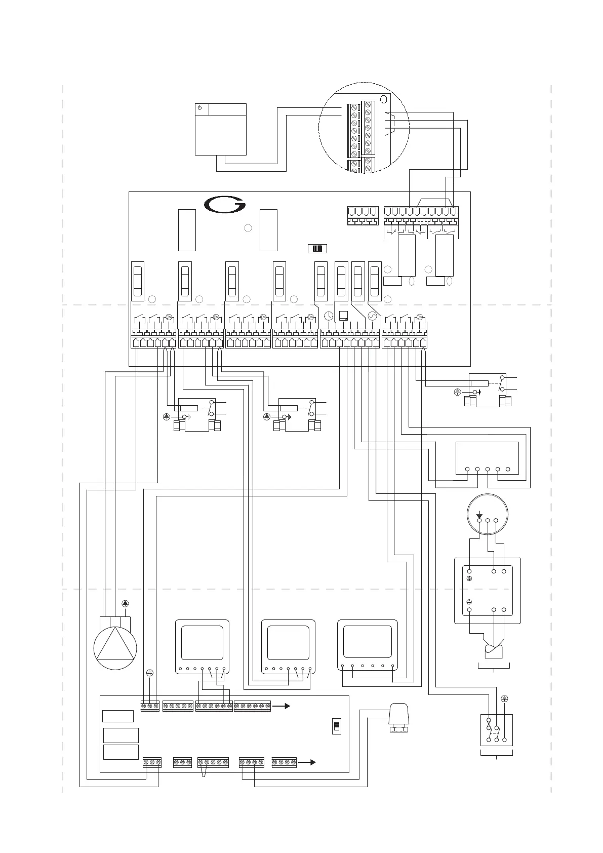
Figure 5-3: Grant QR integrated indirect heat pump cylinder connected to a Grant Aerona³ ASHP, as part of a S-Plan plus type system
with UFH (Grant UH8 Wiring Centre) and a radiator circuit
The control system shown in this diagram shows the “hot water priority” switch on the EP001 wiring centre in the left hand
‘ON’ position. This ensures that the ASHP cannot operate to provide space heating and hot water at the same time.
For information regarding the operation of the Greenbrook T205-C timer shown in this control system wiring diagram, please
refer to Appendix B at the back of these installation instructions.
2
GRANT
EP001 - Wiring centre.
Issue 5
Mains
Power
LED8
LED1
LED2 LED3
LED4 LED7
C2 C1
VAR2
VAR1
LED6
LED5
S1
Hot Water
Priority
RL1
RL2
RL3
RL4
F1 1A
F2
1A
F3
1A F4 1A F5
3.15A F6
5A
F8
1AF7
6.3A
DANGER HIGH VOLTAGE |
All Fuses
230Vac Anti-surge
1 2 3 4
5
8 9 10 11 14
15
16 17 20 21 22 23
N L N L N L
34 35 36 376 7 12
13
18 19 24
L N
33 38
3940414344454647 424849505152
L L L L L N L L L L L N L L L L L N L L L L L N L L L L L N
Spare
Clock Stat
Pump
Clock Stat
Pump
Clock Stat
Pump
Clock Stat
Pump
Clock
Cyl
Stat
Pump
Heating
Hot water
HMI
INOUT
NC2 C2 NO2 NO1 C1 NC1 OP2 OP1
26 27 28 2925 30 31
32
Link
Motor
HW
2-Port Zone Valve
- DHW -
ASHP Terminals
1
2
3
4
5
6
7
8
17
18
19
20
21
22
23
24
25
Hot Water (Yellow)
Common (Red)
Link
Heating (Blue)
Aerona
³
Heat Pump
Motor
HTG
2-Port Zone Valve
- Radiator Circuit -
Do not
connect
Motor
HTG
2-Port Zone Valve
- UFH Circuit -
Do not
connect
Do not
connect
Do not
connect
Do not
connect
Do not
connect
ON
OFF
Digital
Dual Thermostat
L N
C1
Additional Circulator
for UFH Circuit
L N E
Aerona³ Controller
UFH
Actuator
- Zone 1 -
Brown
Blue
L
1 2
E N
S/L
THERMOSTAT ZONE 1
1 2
L L N N
ACTUATORS
Or Gr
L E N
UFH VALVE
Ls E Lr
HEAT
ENABLE
L E N
UFH PUMP
L E N
L L N N
ACTUATORS
ZONE 1 ZONE 2
L E N
MAINS SUPPLY
TIME CLOCK
2
E N
S/L
THERMOSTAT ZONE 2
UFH
RAD
ZONE 8 TYPE
FUSE
5 Amp Anti-Surge
L
1
L
N
A1A2RT1RT2
-
Link
Grant NeoStat
Programmable Room
Thermostat
- UFH Circuit -
Grant UH8 Wiring Centre
Zones
3 to 8
Zones
3 to 8
N L
Hot Water
Immersion
Heater
N L
LOAD
SUPPLY
N L
Greenbrook T205-C
Immersion Timer
(indepently switched and
fused at 13A)
5A
L N E
230V
50HZ
L
N
A1A2RT1RT2
-
Link
Grant NeoStat
Programmable Room
Thermostat
- Radiator Circuit -
CH1CH2CH3
CH4N L
Grant HPIDTM4
DHW Timer
Brown
Blue
Orange
Grey
Orange
Grey
Orange
Grey
G/Y
G/Y
Brown
Blue
Brown
Blue
G/Y
Pre-wired in FactoryInstaller Wiring
Installer Wiring
Grey
Black
Blue
Brown
Brown
Blue
G/Y
E N L
230V
50HZ
Link
(factory fitted)