60
240V
50HZ
L N E
13A
Fuse
1 2 3 4 5 6 7 8 9 10
Pump
Wiring
Centre
Blue
Green/Yellow
Brown
Link
E
N
L
L N E
5A
Fuse
PL N SL
L1 N L2
Four-way plug (comes fitted
to four-way socket on rear
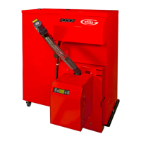
of Grant Spira Hopper)
N
Grant 2-Channel
Wall Mounted
Programmer ESKIT
L 1 2 3 4
OFF OFF ON ON
HW HT HW HT
Frost
Thermostat
Pipe Thermostat
(If fitted)
Use 4-Core flex at least
1.5mm² between junction
box and hopper*
}
Permanent Live
Earth
Neutral
Switched Live
Permanent Live
Neutral
Cylinder
Stat
Grey
Orange
3-Port Mid Position
Zone Valve
Motor
Blue
Green/Yellow
1
C
2
White
13k
2W
270k
0.25W
Room
Stat
2 1 3
Link
Figure 8-10: Heating system controls – Y-plan type system connection diagram
Figure 8-11: Connection of Grant low water
pressure switch (product code: MPCBS62)
PL
SL
N
L1 N L2
Wall mounted
Junction box*
Use 4-Core flex at least
1.5mm² between junction
box and hopper*
Four-way plug (comes fitted
to four-way socket on rear
of Grant Spira Hopper)
}
PERMANENT LIVE
EARTH
NEUTRAL
SWITCHED LIVE
Pressure
Switch
!
NOTE
Earth and some Neutral connections
have been excluded for clarity.
All switches are shown in the closed
position.
!
NOTE
All cable to be 0.75mm
2
minimum
unless otherwise shown.
*See Figure 8-11 for wiring Pressure
Switch Kit for use with plastic pipe in
installation

 Loading...


