41
7 Flue System and Air Supply
7.1 Air Supply
The Grant Spira wood pellet boiler
draws air for combustion from the room
in which it is located.
Any room or space containing an
appliance must have sufficient
permanent air supply to ensure correct
combustion of the fuel and effective
operation of the flue system (i.e. to
discharge of combustion products to
the open air).
For a boiler operating with a draught
stabiliser:
• If design air permeability
>5.0m³/(h.m²) then:
• 300mm²/kW for the first 5kW
of appliance rated output
• 850mm²/kW for balance of
appliance rated output.
• If design air permeability ≤5.0m³/
(h.m²) then:
• 850mm²/kW of appliance
rated output*.
*
It is unlikely that a dwelling constructed
prior to 2008 will have an air permeability
of less than 5.0m³(h.m²) at 50 Pa unless
extensive measures have been taken to
improve air-tightness. See Appendix F of The
Building Regulations Approved Document J.
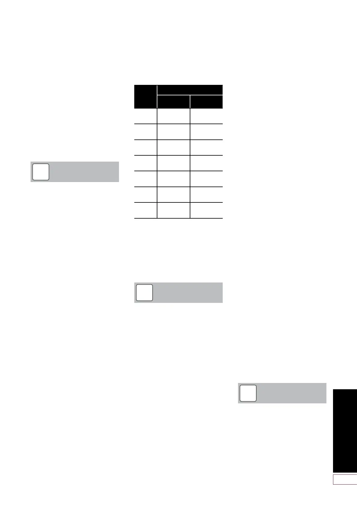
To achieve this, the following minimum
vent openings are required:
7.2 Flue Terminal Position and
Clearances
The Grant Spira wood pellet boilers
have high operating efficiencies and low
flue gas temperatures. Only the Grant
Biomass twin-wall insulated flue system
must used with the Grant Spira boilers.
The following points MUST be taken
into consideration with regard to the
design and installation the flue system:
• Grant recommends that the flue is
vertical for a minimum distance of
600mm (measured from the top
of the boiler) before any elbow.
However, this is not essential for
the operation of the boiler.
• There must NOT be any change of
direction greater than 45° from the
vertical, e.g. two 45° elbows must
not be used together to form a 90°
elbow.
• The flue system must NOT include
any horizontal sections of flue.
• Grant recommends that an
adjustable flue extension be fitted
in the flue system as close to the
boiler as possible, to enable the
flue system to be disconnected
from the boiler flue connection, as
and when required, for future boiler
maintenance.
• The weight of the flue system
must NOT be carried by the boiler,
but must be supported using the
various support options available
in the Grant ‘Biomass’ flue system.
Refer to Section 7.4.5.
• The minimum distance between
the outer surface of any part of the
flue system and any combustible
material is 60mm. Refer to Section
7.3 for flue system designation.
A minimum clearance of 25mm
around the flue is required for the
fitting/removal of locking bands.
• The flue terminal should be
located in a downdraught free
area, i.e. above the roof, where
it can discharge freely and not
present a fire hazard whatever the
wind conditions. The flue outlet
positions shown in Figure 7-1 (from
Approved Document J) can meet
this requirement.
• The heights and separation
distances shown in Figure 7-1
may have to be increased in
particular cases, e.g. where high
wind exposure, surrounding tall
buildings, or adjacent trees can
cause adverse wind effects.
• The boiler flue cannot terminate
into an existing brick or clay lined
chimney. All masonry flues must
be lined using the Grant ‘Biomass’
system stainless steel flexible flue
liner.
• No other appliance can be
connected to the boiler flue.
• Any condensate in the flue can run
back into the boiler. A condensate
drain at the base of the flue
system is not required as the flue
system is designed to allow the
condensate to run back into the
boiler.
!
NOTE
The ventilation area provided
must be in accordance with the
requirements of The Building
Regulations Approved Document
J – Section 2: Appliances burning
solid fuel.
Boiler
model
Minimum vent open area
>5.0m³/(h.m²)
≤5.0m³/(h.m²)
5-18kW 125.5 cm²
(20 in²)
153 cm²
(24 in²)
6-26kW 193.5 cm²
(30 in²)
221cm²
(35 in²)
9-36kW 278.5 cm²
(44 in²)
306 cm²
(48 in²)
11-44kW 346.5 cm²
(54 in²)
374 cm²
(58 in²)
12-52kW 414.5 cm²
(65 in²)
442 cm²
(69 in²)
15-62kW 499.5 cm²
(78 in²)
527 cm²
(82 in²)
18-72kW 584.5 cm²
(91 in²)
612 cm²
(95 in²)
!
NOTE
The flue installation must be in
accordance with the requirements of
The Building Regulations Approved
Document J – Section 2: Appliances
burning solid fuel.
The only flue suitable for use with
the Grant Spira condensing wood
pellet boiler is the Grant Biomass
twin-wall insulated conventional flue
system.
This 125mm (5”) ‘Biomass’ flue
system is suitable for the 5-18kW,
6-26kW and 9-36kW Spira models.
For the 44kW, 52kW, 62kW and
72kW double boiler installations
each boiler must have a separate
flue system.
!
NOTE

 Loading...


