Page 27Section 9: Flue System and Air Supply
The boiler is supplied with a ue terminal. Refer to Section 4.7 for
tting details.
As an alternative to the terminal supplied, there are three external
ue systems that can be used with the Vortex Pro Outdoor Combi
boiler, all available from Grant UK.
PLUME DIVERTER KIT
This vertical system is availabe to purchase from Grant UK and
is intended to be retrotted to the ue terminal supplied with
the boiler, in order to terminate the ue in a more preferable or
permissable location.
GRANT GREEN SYSTEM
VERTICAL:
This vertical twin wall stainless steel insulated system replaces
the low level terminal supplied with the boiler, and may terminate
at high level or vertically as required.
HORIZONTAL:
This option allows the extension of the ue system in the
horizontal plane in order to terminate the ue in a more preferable
or permissable location.
These two systems are described in this section.
9 FLUE SYSTEM AND AIR SUPPLY
9.1 AIR SUPPLY
A sucient permanent air supply to the boiler should be provided
for the following reasons:
• For proper combustion of fuel and eective discharge of
combustion products to the open air.
• For the ventilation of any conned space in which the boiler
is installed to prevent overheating of the boiler and any
equipment in and near the boiler.
Grant external boilers draw their air supply via the ventilation
holes in recessed top edge of the front door of the boiler casing.
These ventilation holes must not be obstructed.
Further details may be obtained from BS 5410-1.
9.2 PLUME DIVERTER KIT
Should the low level ue supplied with the boiler be discovered
to cause a plume nuisance after its installation, a plume diverter
kit is available to purchase from Grant UK for the purpose of
re-directing the ue gases to a higher level (according to the
minimum clearances shown in Figure 9-5).
The plume diverter kit has been designed to be retrotted to the
low level ue supplied with the external boiler by attaching the 90°
elbow supplied with the kit directly to the boiler ue terminal.
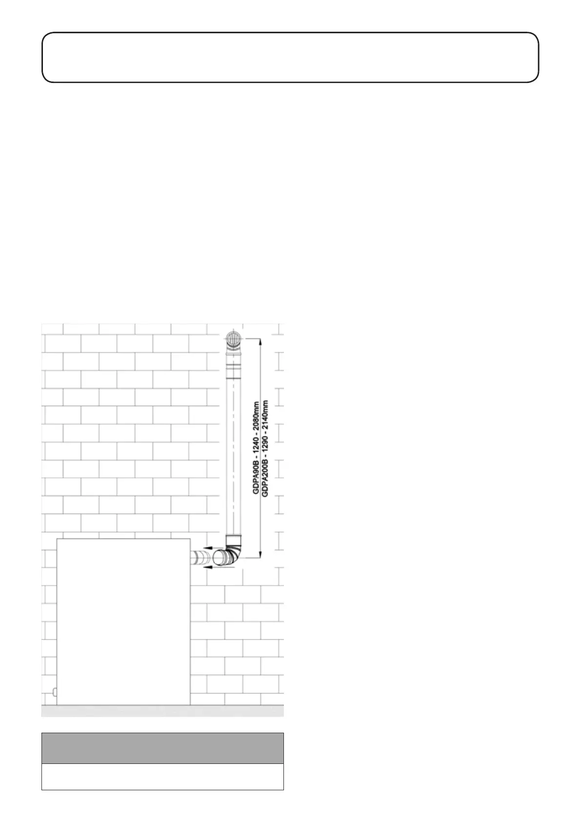
This kit is available in two sizes, product codes as follows:
• GDPA90B - suitable for installations of up to 26kW (maximum
vertical length of 2.08m)
• GDPA200B - suitable for installations ranging from 26-70kW.
(maximum vertical length of 2.14m)
While every eort has been made to make this retrot as simple
as possible for the installer, it is necessary for the installer to drill
an 8mm hole in the side of the existing ue terminal to ensure
that the condensate produced by the ue gases during normal
operation drain back into the boiler.
It is also necessary for the installer to spot drill two 3mm holes in
the existing ue terminal. With the plume diverter starter elbow
in its nal position on the existing ue terminal, use the holes in
either side of this elbow as a guide to drill the two holes in the
terminal and x the elbow to the existing terminal by driving one of
the two self-tapping screws provided into each hole.
More detailed installation details for this system can be found in
the tting instructions supplied with the kit.
Please see Figures 9-1 and 9-2 for a visual representation of
the plume diverter kit tted onto a Grant Vortex Pro Outdoor
Combi boiler and Table 9-1 for the distance of the plume diverter
centre line from an external wall when correctly tted to the boiler
(Dimension A in Figure 9-2).
A series of extensions and other accessories are available for use
with this kit. Please contact Grant UK for further information.
Figure 9-1: Plume diverter kit - Front View
! NOTE !
Ensure that the Plume Diverter Kit starter elbow is fully
pushed onto the external boiler ue terminal. See above.