Page 58
A1.1 WILO YONOS PARA RS RKC
CIRCULATING PUMP
A1.1.1 PUMP SPECIFICATION
Table A1-1: Pump specication
Make and model
Wilo Yonos PARA RS 15/7.0 RKC
FS 130 12
Construction
Pump housing
Cast iron (with cataphorisis treat-
ment)
Impellar PP composite with GF 40%
Pump shaft Stainless Steel
Bearing Carbon, metal impregnated
Protection Class IPx4D
Insulation Class F
Motor Protection Integrated
Performance
Max. delivery head 7.2m @ Q = 0 m
3
/h
Max. volume ow 3.3 0 m
3
/h
Minimum suction head @ 50/95°C 0.5/4.5m
Power consumption @ 1 - 230V 3-45W
Nominal Motor Power 37W
Current @ 1 - 230V 0.028 - 0.44 A
Energy Eciency Index (EEI) ≤ 0.20
Speed 800-4650 rpm
Settings
∆P-variable (1-7m head) and Con-
stant Speed (I, II and III)
Application
Maximum Static Pressure PN6
Temperature range @ maximum
ambient temperatures
Maximum ambient temperature
57°C: 0 to 95°C
Maximum ambient temperature
59°C: 0 to 90°C
Maximum ambient temperature
67°C: 0 to 70°C
Approved Fluids
Heating Water
Water/Glycol - Max 1:1 (above 20%
check pumping data)
A1.1.2 PUMP CONTROL PANEL
Wilo Yonos PARA RKC circulating pumps have two possible
setting modes:
• Constant speed with three pump speed settings (I, II and III)
• Variable pressure (∆p-v) with pump head adjustable between
1 and 7m head
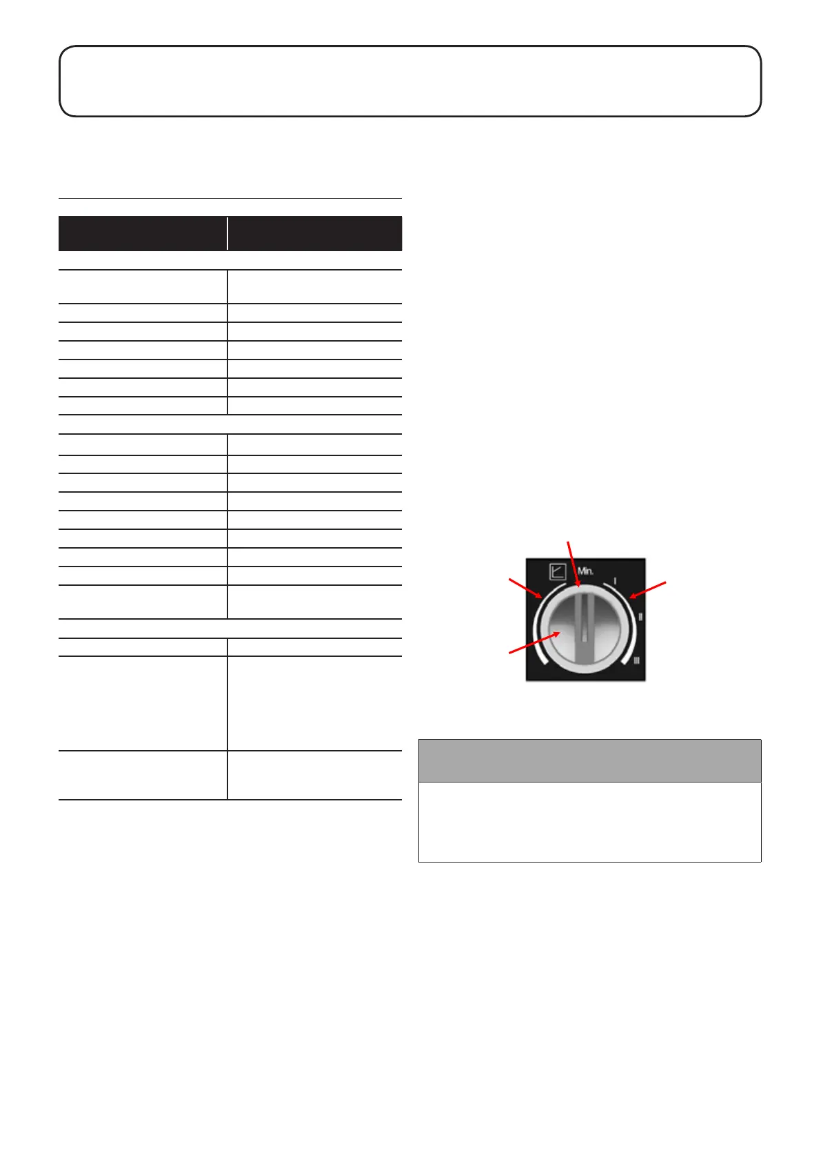
Figure A1-1 shows the pump control panel with the red selector
knob.
Constant Speed Mode (I, II, III)
This is the default setting of the pump and as such is
recommended by Grant for heating systems. In this mode the
pump speed is not automatically regulated (as with the Variable
Pressure Mode), but operates constantly at one of the three
possible speeds (set using the red selector knob on the pump
control panel).
Variable Pressure Mode (∆p-v)
In this mode the electronic control changes the dierential
pressure setpoint to be maintained by the pump in a linear fashion
between Hs (the value set using the red selector knob on the
pump control panel) and ½ Hs. The dierential setpoint varies
linearly with the volume ow Q.
A1.1.3 INDICATOR LED
The pump is tted with an indicator LED. This is located around
the circumference of the red selector knob. See Figure A1-1
below. This indicates the operating status of the pump and will
be illuminated green when the pump is operating normally. This
indicator LED can assist in diagnosing and rectifying faults. Refer
to Section A1.2.
A1.1.4 SETTING THE PUMP CONTROL MODE
Set the pump to one of the two operating modes as follows:
Constant Speed Mode (I, II, III)
Grant recommends this operating mode for the pump.
To set the pump to the ‘Constant Speed’ mode, the pointer on the
red selector knob must be set to the RIGHT of the mid position.
Refer to Figure A1-1.
Set it to point at the required speed setting, I, II or III as required,
ensuring that there is adequate ow to distribute the heat from the
boiler whilst avoiding high water velocities causing noise in the
pipework.
Variable Pressure Mode (∆p-v)
To set the pump to the ‘Variable Pressure’ mode the pointer on
the red selector knob must be set to the LEFT of the mid position.
Refer to Figure A1-1.
The further anticlockwise it is set the greater the pressure head
setting of the pump – from 1m to 7m head.
If this mode is to be used, set the selector knob at a pressure that
represents the maximum pressure (head) loss for the heating
system in question.
Variable Pressure Mode
settings: 1 to 7m head
Indicator LED
Constant Speed Mode
settings: I, II, III
Red selector knob
Figure A1-1: Pump control panel with red selector knob and LED
indicator
APPENDIX A1 WILO YONOS PARA RS RKC
CIRCULATING PUMP
Appendix A1: Wilo Yonos PARA RS RKC
! NOTE !
Both circulating pumps on all Grant Vortex Combi boilers
come factory set at Constant Speed Mode III and should be
left set on this setting.
The heating circuit circulating pump should be set by the
installer to suit the system.