2.2 BURNER SETTINGS
Table 2-2: Burner settings
Boiler
models
(burner
type)
Heat output
Nozzle
Oil
pressure
(bar)
Smoke
No.
Burner
head
type
Burner
head/
air disc
setting
Distance
D ⁸ (mm)
Fuel
ow rate
(kg/h)
Flue gas
temp.
(°C)
CO
2
(%)
Flue
gas
VFR ‡
(m³/hr)
(kW) (Btu/h)
Outdoor
Combi 21
(Riello
RDB2.2 BX
E15/21)
21.0 71,600 0.60/60°ES 8.0 0 - 1 BX 500 Disc: C 13 1.84 75 - 80 12.5 23.0
Outdoor
Combi 26
(Riello
RDB2.2 BX
VC26)
26.0 88,700 0.75/60°ES 8.5 0 - 1 BX 500 N/A 15 2.16 75 - 80 12.5 28.5
Outdoor
Combi 36
(Riello
RDB2.2 BX
VC36)
36.0 122,800 1.00/60°ES 9.0 0 - 1 BX 700 N/A 17.5 2.99 75 - 80 12.5 39.5
Notes:
‡ Flue gas VFR: Flue gas volumetric ow rate
1. The data given above is approximate only and is based on the boiler being used with a low level balanced ue.
2. The above settings may have to be adjusted on site for the correct operation of the burner.
3. Gas Oil is NOT suitable for use with Grant Vortex boiler range
4. The ue gas temperatures given above are ± 10%.
5. When commissioning, the air damper must be adjusted to obtain the correct CO
2
level.
6. The combustion door test point may be used for CO
2
and smoke readings only. Do not use this test point for temperature or eciency readings.
7. When commissiong the Combi 21, the position of the air adjuster disc should be checked. Refer to Section 10.3 (Air Adjuster Disc).
8. Refer to Section 10.2 for information on how to set Distance D (Figure 10-5).
2.3 FLUE GAS ANALYSIS
To allow the boiler to be commissioned and serviced, the boiler is supplied with a combustion test point on the front cleaning door.
When this test point is used please note the following:
• The test point is for CO
2
and smoke readings only.
• The boiler eciency and temperature must be taken from the ue test point on high level, vertical and conventional ue adaptors.
• Concentric low level ues do not contain a test point. The temperature and eciency readings must be taken from the ue terminal.
Section 2: Technical Data Page 7
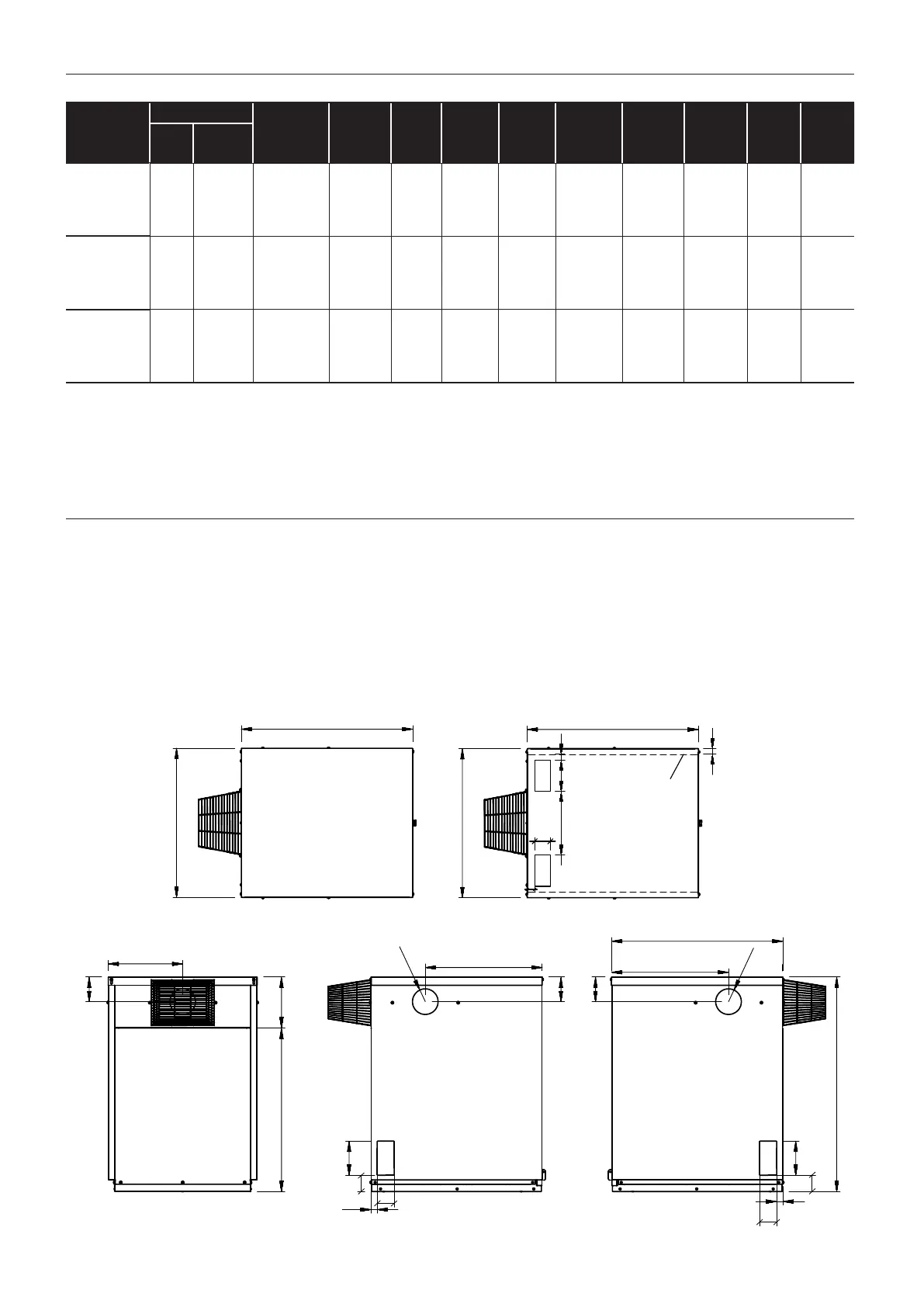
755
755
329
516
516
REAR VIEW
27
LEFT SIDE VIEW
RIGHT SIDE VIEW
75
75
27
108
720 223
657
150
72
108
108
150
72
944
R 56
R 56
755
BASE VIEW
657
Dashed lines
show footprint
of base
25
25
150
256
75
33
PLAN VIEW
Figure 2-1: Vortex Pro Outdoor Combi Dimensions
2.4 BOILER DIMENSIONS