4
Installation
Frame Interface
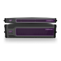
Kaleido-MX functional block diagram
Frame Interface
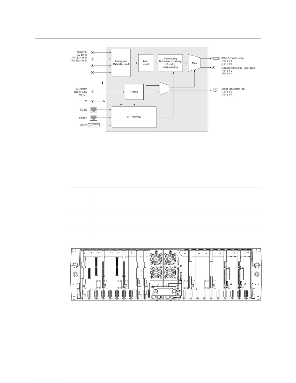
Front of the Kaleido-MX (3RU) frame
When the frame door is opened, the front of the Kaleido-MX (3RU) unit is visually divided
into three sections:
When the frame door is closed, the status LED on each of the cards in the frame is visible via
a light pipe in the door. No other controls or indicators are present.
Left side Card slots 1–10 are laid out vertically. Input cards require 3 slots. A GPI-1501 card
occupies slot number 1, and a VDA-1002 card occupies slot 9. Slot number 2 is
reserved for a second GPI-1501 card (optional), and slot number 10 is reserved for a
REF-1801 card (optional).
Center The controller card with its attached control panel occupies the unnumbered slot
to the right of the PSU and fan assemblies.
Right side Card slots 11–20 are laid out vertically. Input cards require 3 slots. Output cards
require 2 slots.
 Loading...