23
Never make adjustments with the
engine running.
LOSS OF POWER IN THE DRIVE
SYSTEM
Check the fl uid level and be sure the proper
amount of fl uid is in the expansion tank. The
cooling fi ns and fan blades should be clean
and free of foreign matter.
NO POSITIVE NEUTRAL POSITION
If drive wheels travel forward or backward
when the steering lever is in swing-out posi-
tion (neutral), adjustment is required.
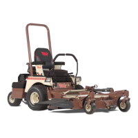
NEUTRAL ADJUSTMENT
(Refer to Fig. 6 and illustration page on 31)
1. Block up under tractor frame so both drive
wheels are off the ground.
2. Make sure parking brake is released.
3. Remove linkage rod (item 28 or 29) from
transmission control arm (item 17 or 18).
4. Place steering levers in the neutral swing-
out position and start engine.
5. If either of the drive wheels turn, proceed
with the following adjustment.
6. Locate the return mount (item 37) with
the adjustment plate (item 71) bolted to
it. The right plate adjusts the right side
while the left plate adjusts the left side.
Loosen the .312-24 x .5 bolt (item 66) lo-
cated in the upper corner of plate. Insert
a screwdriver into the triangle shaped slot
and rotate adjustment plate until neutral is
achieved. Tighten bolt.
7. Repeat procedure on other side transmis-
sion.
8. Reinstall linkage rod in control arm. If rod
end (item 26) does not reinstall into con-
trol arm without moving the control arm,
adjust length of linkage rod until it slides
into control arm to assure neutral adjust-
ment will be maintained when linkage is
connected.
9. Test drive machine for straight line travel
with both levers full forward. If travel is not
in a straight line, adjust the steering lever
stop on the side that is the fastest i.e.: if
machine goes to the left, adjust the right
steering stop to slow down the right trans-
mission until travel is straight ahead.
ADJUSTMENTS AND TROUBLESHOOTING
Fig. 6
37
71
66
Triangle
Shaped Slot
13044
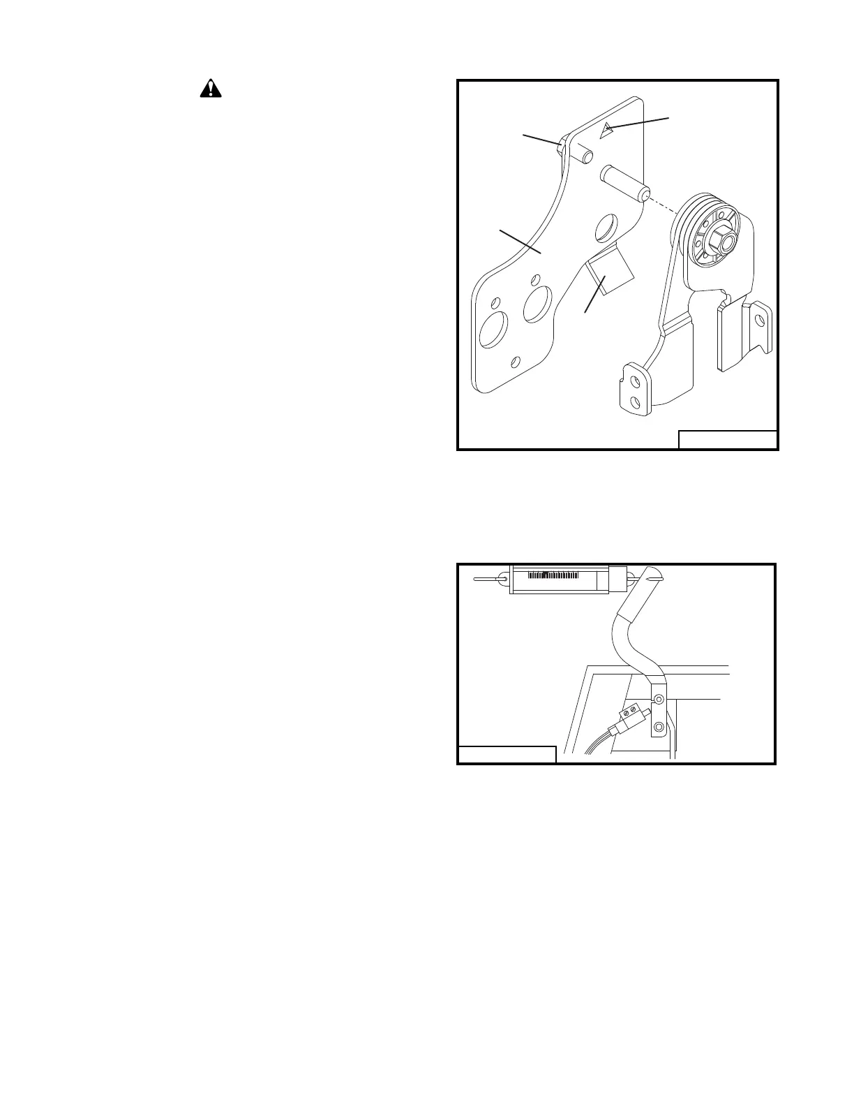
CAUTION
Fig. 7
PARKING BRAKE ADJUSTMENT
(Refer to Fig. 7 and illustration on page 33)
Adjust the right and left brake individually.
Disconnect the right brake linkage rod (item
25). Adjust the linkage pin (item 27) to the left
brake until it takes 14 lbs of pull at the top of
the hand lever to apply the parking brake. Ad-
justment of brake linkage rod (item 22) may
also be required. Connect the right brake
linkage.
Disconnect the left brake linkage rod and ad-
just the linkage pin attached to the right brake