25 / 32
S3084_S3086_S3078_S3085_MP_V1
Graphical display of telemetry data
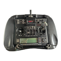
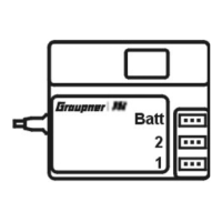
To display the telemetry data, please read the instructions of your
remote control system or of the SMART-BOX.
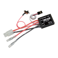
This display visualizes the data of the speed controller. It has the fol-
lowing meaning from the top, left side):
Value Explanation
V
Left value: current battery voltage
Right value: lowest battery level since the device has
been switched on
Temp.°C
Upper indicator: ESC lower indicator: Motor (only
if supported, otherwise 0)
Left value: current ESC/motor temperature
Value in brackets: maximum ESC/motor temperature
since the device has been switched on
mAh
used battery capacity (is actually not supported)
A
Central and column indicators: actual current
Right value: maximum current since the device has
been switched on
rpm
Central and column indicators: rpm of the connected
motor
Right value: maximum rpm since the device has been
switched on
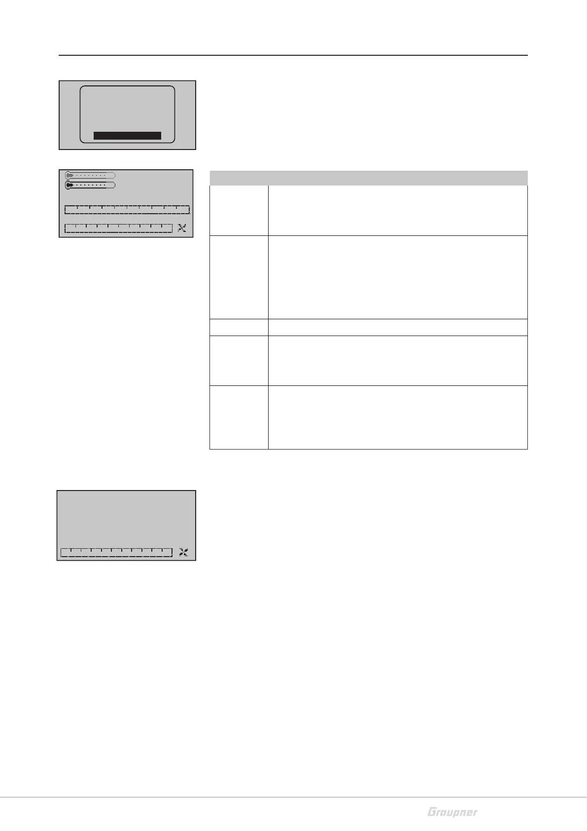
Rpm indicator
This indicator shows the actual rpm of the motor connected to the
speed controller. The correct indication depends on the correct input
of the gear ratio and the number of poles of the motor
RX–S QUA: 100%
RX–S ST : 100%
TX–dBm: 33dBm
RX–dBm: 33dBm
RX–SPG.:4.8 TMP
V–PACK: 10ms
CH OUTPUT TYPE:ONCE
EMPFÄNGER
GENERAL
ELECT. AIR
VARIO
GPS
AIR ESC
0
0
0rpm
0.0A
0.0A
0
0mAh
0( 0)°C
0.0V/ 0.0V
0( 0)°C
U/min
0
0
 Loading...