Do you have a question about the GRAUPNER HoTT and is the answer not in the manual?
Procedure to bind a Graupner HoTT 2.4 GHz receiver to a transmitter, including multi-receiver setup.
Method for checking the effective radio range of the system, essential before flight.
Default 'Hold' mode and programming throttle response for fail-safe situations to prevent loss of control.
Understanding the audible warning for weak signal and its implications with low voltage or temperature.
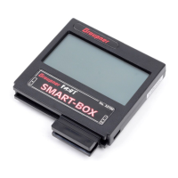
Connecting the SMART-BOX for firmware updates and system configuration.
Connecting servos and power supply to the receiver, noting socket polarity and specific model requirements.
System warnings for low receiver voltage (below 3.8V) and extreme temperatures (-10°C/+70°C).
Procedure for updating receiver firmware using a PC, USB interface, and adapter lead.
Steps to update firmware for transmitter RF module and receiver using PC utility.
Using the upgrade studio, download process, and crucial post-update receiver initialisation.
Manufacturer's declaration of compliance with radio and telecommunications equipment regulations.
FCC compliance, warnings, RF exposure, and proper disposal of electronic equipment.
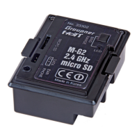
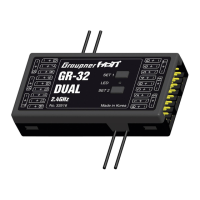
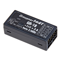
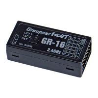
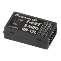
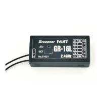
List of available receivers (GR-12S to GR-24) and the GPS/Vario module with order numbers.
Details on General Air-Module, sensors (Temp, RPM), and SMART BOX with order numbers.
This document describes the Graupner HoTT 2.4 GHz radio control system, covering its functions, usage, and maintenance features. The system is designed for remote control models, offering reliable communication and various programmable options for enhanced safety and control.
The Graupner HoTT 2.4 GHz system operates as a remote control unit for models, comprising a transmitter and one or more receivers. Its primary function is to transmit control commands from the user to the model's servos and other electronic components. A key feature is its "binding" process, which establishes a secure link between a specific transmitter and receiver(s). This binding only needs to be performed once for each transmitter/receiver combination, ensuring that the system operates exclusively with its designated components. The system also supports binding multiple receivers to a single transmitter for a particular model, allowing for distributed control functions and enhanced redundancy. In such a setup, one receiver acts as the "Master" for telemetry data transmission, while others operate in "Slave" mode.
Telemetry is a significant aspect of the HoTT system, providing real-time feedback from the model to the transmitter. This includes warnings for low receiver voltage and temperature, ensuring the user is aware of critical operational parameters. The system generates audible alarms for these conditions, prompting the user to take corrective action, such as landing the model.
A crucial safety feature is the "Fail-Safe" function. In the event of signal loss or interference, the receiver can be programmed to adopt predefined servo positions or maintain the last valid positions ("Hold" mode). This is particularly important for throttle channels, which can be set to "idle" for engine-powered models, "stop" for electric models, or "Hold" for helicopters, preventing uncontrolled flight and potential damage or injury.
The system also incorporates a "Range Check" mode, which allows users to verify the effective radio range before each flight. This mode reduces the transmitter's output power, enabling a practical assessment of the control link's reliability over a safe distance.
For advanced configuration and updates, the system supports connection to a SMART-BOX (Order No. 33700) and a PC. This allows for detailed channel mapping, firmware updates, and customization of various settings, including fail-safe parameters and telemetry thresholds.
Operating the Graupner HoTT 2.4 GHz system involves several user-friendly features designed for ease of use and safety.
Binding Procedure: To bind a receiver to a transmitter, both units are switched on. The BIND / RANGE button on the transmitter and the SET button on the receiver are pressed and held simultaneously. The LEDs on both units provide visual feedback: constant glow on the transmitter LEDs and a flashing red LED on the receiver indicate the binding process is active. A constant green LED on the receiver signifies successful binding, typically within ten seconds. If the red LED continues to flash, the binding has failed and needs to be repeated. For multiple receivers, each is bound individually, with the last bound receiver becoming the Master.
Fail-Safe Programming: The Fail-Safe function can be programmed using the BIND / RANGE button on the transmitter. By holding this button while switching on the transmitter, users can cycle through different Fail-Safe modes:
Visual and audible cues (beeps and LED changes) guide the user through the programming process. It's important to note that programming Fail-Safe via the button resets SMART-BOX settings and the Country setting to Universal, requiring re-selection if necessary.
Range Checking: Before each flight, a range check is recommended. The bound receiver is installed in the model, and both transmitter and receiver are switched on. The transmitter's BIND / RANGE button is pressed and held to activate range-check mode, indicated by alternating flashing red and green LEDs and a regular beep. The user then walks away from the model, constantly operating the transmitter sticks, to identify any interruptions in the control link. The ground range should be at least fifty meters for safe operation. The mode terminates automatically after ninety seconds or manually by pressing the BIND / RANGE button again.
Telemetry Warnings: The system provides audible warnings for critical conditions. A steady beep every second indicates low receiver voltage (below 3.8 V) or extreme receiver temperature (below -10°C or above +70°C). These thresholds can be customized via the TELEMETRY menu on the transmitter or using the SMART-BOX. A range warning, also an audible beep, signals a weak receiver signal in the downlink channel, prompting the user to fly the model closer.
Connections: Servos are plugged into numbered sockets on the receiver, observing polarity (brown wire for negative, red for positive, orange for signal). The "- +/B" socket is for the battery, and a Y-lead can be used to connect a servo in parallel. For high-power servos, power supplies should be connected to the vertical ports of the receiver. The "T" socket on the left-hand end is for optional telemetry sensors and firmware updates.
The Graupner HoTT 2.4 GHz system includes features for maintenance, primarily focused on firmware updates and initialisation.
Firmware Updates: Firmware updates for both the transmitter RF module and the receiver can be performed via a PC running Windows XP, Vista, or 7. This requires a USB interface (Order No. 7168.6) and an adapter lead (Order No. 7168.6A or 7168.6S). The necessary programs and files are available from the Graupner website. The update process involves connecting the device to the PC, starting the "Firmware Upgrade Graupner Studio" software, selecting the correct COM port, and browsing for the firmware file (ending in *.bin). The software guides the user through the process, displaying progress and status messages. During the update, both red and green LEDs on the receiver glow constantly; upon completion, the red LED flashes, and the green LED goes out.
Initialisation (Factory Reset): After a firmware update, or if settings need to be reset, the device must be initialised. This is done by pressing and holding the SET button on the receiver while switching it on. The red and green LEDs will blink, then after about three seconds, the green LED will go out, leaving only the red LED flashing. Releasing the SET button completes the initialisation. It is crucial to note that initialisation erases ALL user-entered settings, including those programmed via the SMART-BOX, requiring them to be re-entered.
Environmental Protection: The manual emphasizes responsible disposal of the product at the end of its useful life. It should not be discarded with ordinary domestic waste but taken to a local collection point for recycling electrical and electronic equipment. Batteries should also be removed and disposed of separately. For R/C models, electronic parts like servos, receivers, and speed controllers must be removed and disposed of at corresponding collection points for electrical scrap.
General Care: The manual advises against forcing plugs into sockets, as the connector system is polarised. It also stresses the importance of keeping the transmitter aerial at least 15 cm away from receiver aerials during switch-on or adjustment to prevent receiver overload. If overload occurs, indicated by a red LED on the receiver and a transmitter beep, increasing the distance between aerials will resolve the issue.
These features collectively ensure the Graupner HoTT 2.4 GHz system is not only functional and safe but also maintainable and adaptable to evolving user needs and technological advancements.
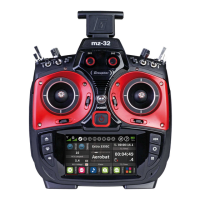
| Frequency | 2.4 GHz |
|---|---|
| Telemetry | Yes |
| Protocol | HoTT |
| Display | LCD |
| Battery | LiPo |
| Model Memory | 30 models |
| Channels | 12 |
| Modulation | Digital |