FR - 13
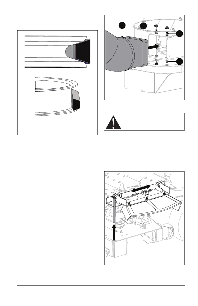
IMPORTANT: Ensure flat side of V-belt
contacts idler pulley and the V-side of V-belt
contacts split pulley as shown in Figure 14.
Belt must be correctly adjusted for blower to
operate properly. See Adjust Belt Tension on
page 18.
INSTALL HOSE ADAPTER
1. Install hose adapter (Item 14) and secure
with two 5/16 x 1" round head square
neck bolts (Item 17), two 5/16 x 3/4”
round head square neck bolts (Item 16)
and four nyloc flange nuts (Item 15).
Install 3/4” bolts on the top and 1" bolts on
the bottom. Bolts are installed from the
inside with the nuts on the outside. See
Figure 15.
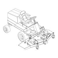
INSTALL BLOWER ASSEMBLY
NOTICE: Install baffle before installing blower
assembly. See Installation Kits on page 19.
1. Remove and retain 3/8 x 2" hex bolt
retaining discharge chute assembly.
Remove discharge chute. Retain all parts
for operation without bagger. See
Figure 16.
2. Position blower assembly at discharge
chute opening.
Idler Pulley
Split Pulley
Figure 14
CAUTION: Ensure blower
assembly covers the discharge
chute opening.