EN - 25
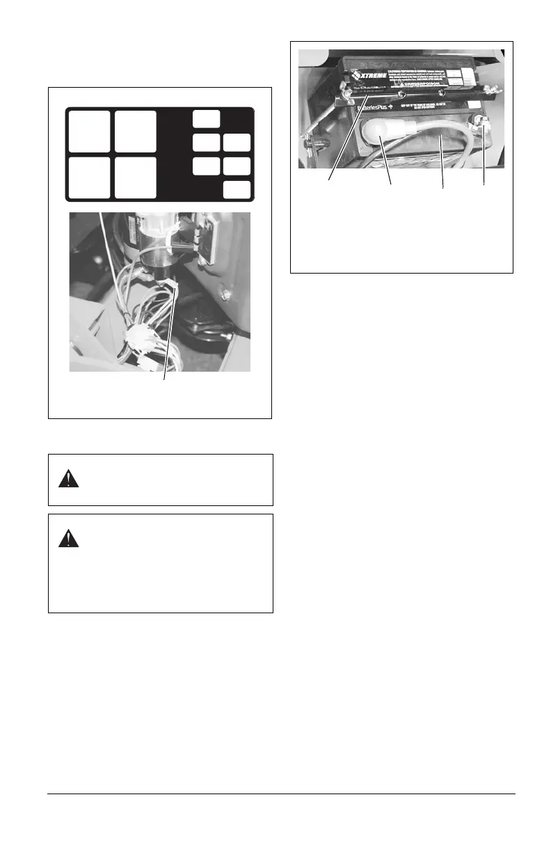
FUSE BLOCK
The fuse/relay panel is located behind the
rear access panel, below the control panel.
BATTERY
Cleaning the terminals is the only regular
battery maintenance required.
Remove Battery
1. Shut off engine. Engage parking brake.
Remove the ignition key.
2. Place rear access panel in the service
position.
3. Disconnect cables from battery (negative,
then positive). See Figure 18.
4. Remove hold-down bracket and remove
battery.
Replace Battery
1. Replace battery and secure with hold-
down bracket.
2. Reconnect cables to battery (positive,
then negative). Position boot over
positive terminal.
Clean Battery
Keep battery and terminals clean. Inspect
every 100 operating hours or monthly for best
performance.
1. Remove battery from unit.
2. Clean terminals and battery cable ends
with wire brush.
3. Coat terminals with dielectric grease or
petroleum jelly.
4. Replace battery.
Charging the Battery
IMPORTANT: DO NOT fast charge. Charging
at a higher rate will damage or destroy
battery. ONLY use an automatic charger
designed for use with your battery.
ALWAYS follow information provided on
battery by battery manufacturer. Contact
battery manufacturer for extensive
instructions to charge battery.
1. Remove battery from unit. See Remove
Battery on page 25.
2. Place battery on bench or other well-
ventilated place.
3. Connect positive (+) lead of charger to
positive (+) terminal, and negative (–)
lead to negative (–) terminal.
4. Charge battery according to charger and
battery manufacturers’ instructions.
WARNING: AVOID INJURY. Read
and understand entire Safety
section before proceeding.
WARNING: Battery posts,
terminals and related accessories
contain lead and lead compounds,
chemicals known to the State of
California to cause cancer and
reproductive harm. Wash hands
after handling.
START/RUN
RELAY
STARTER
SOLENOID
RELAY
OPERATOR
PRESENCE
TIME DELAY
RELAY
PTO
RELAY
10A
CONTROLS
FUSE
20A
CHARGING
FUSE
10A
PTO
FUSE
15A
AUXILIARY
FUSE
10A
TIME DELAY
FUSE
15A
ACCESSORY
FUSE
07700114
Figure 17
Fuse Block Diagram
Harness Main Fuse Location
Figure 18
1. Negative Terminal
2. Positive Terminal
3. Battery
4. Hold Down Bracket
2
3
1
4