D Series Modular Air-cooled Scroll Chillers
40
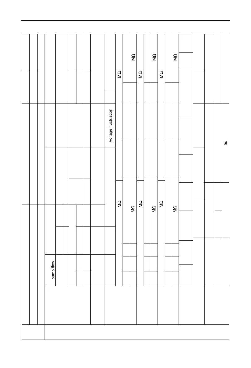
Appendix A: Inspection Records Prior to Commissioning
Installation
Location Min. distance from barriers >2m (Ref.)
Foundation(Concrete/Steel frame ) Shock absorbe r
Arrangement Highest point and lowest point >2m (Ref.)
Routine Check
Chilled water
pipeline
Water
Shutoff valve (On/O ff) Drain valve (On/O ff)F ilter (On/Off) Air release valve (On/O ff)
InletO utlet
Pressure gaug eT hermometer
Flow switch
state
Insulation
state
Shutoff valve state
Flushing times Water quality
InletO utletI nlet Outlet
Load FCU
Air supply
outlet
Air
discharge
state
Air conditioning space
insulation stat e
Refrigeration load
state
Power supply
Supply voltage
(V)
Allowable range 380~400 V %A llowable value <5%
Interphase insulation resistance
P hase-ground insulation resistance
RabR bc Rac Min. allowable valu eR ag RbgR cg Min. allowable valu e
1
1
Insulation of the
whole unit (main air
switch)
Interphase insulation resistance
P hase-ground insulation resistance
R12R 23 R13 Min. allowable valu eR 1g R2gR 3g Min. allowable valu e
1
1
Insulation of
the compressor
(terminal block )
Interphase insulation resistance
Phase-ground insulation resistance
R12R 23 R13 Min. allowable valu eR 1g R2gR 3g Min. allowable valu e
1
1
Refrigeration
system
Repair
brazing
Vacuuming
(MPa)
Max.
allowable
value
0.0080MPa Duration (min)> 30min
System I balance
pressure(Mpa)
System
Ⅱ
balance
pressure (MPa)
Ambient temp
(
℃
)
Control and
protection devices
Power supply monitor
(3Ph)
Leaving water temp (
℃
)V acuuming stop tim e
SetpointS etpointD eviation Setpoint
380~400V
Appendix B: Trial Run and Commissioning Records