Do you have a question about the Gree LSQWF65M/N-M and is the answer not in the manual?
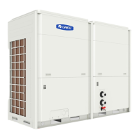
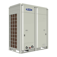
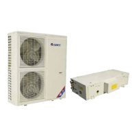
Lists available chiller models with their specifications and appearance.
Explains the meaning of codes and numbering used in model names for identification.
Details the key features and performance benefits of the air-cooled scroll chiller.
Provides comprehensive technical specifications, operating ranges, and electrical data.
Illustrates refrigerant and water piping configurations for cooling and heat pump modes.
Visualizes the operational logic, including cooling and heating modes, for system control.
Explains the core control principles governing compressors, fans, and valves for system operation.
Describes the function, operation, display, and menu structure of the controller.
Outlines essential document checks, model verification, and damage inspection pre-installation.
Specifies requirements for the unit's location, considering fresh air, foundation, and space.
Provides safety warnings and critical considerations for proper unit installation.
Details procedures for mounting the unit using shock pads and bolts for stability.
Lists the physical dimensions (length, width, height) of the chiller units in millimeters.
Specifies required clearances around the unit for adequate airflow and maintenance access.
Illustrates the standard layout, components, and connections of the water piping system.
Explains unit operation with glycol solutions and factors affecting freezing point and performance.
Covers principles, design considerations, and diagrams for electrical connections and safety.
Lists error displays, descriptions, signal sources, and control logic for diagnosing faults.
Provides step-by-step diagnostic flowcharts for common system protection and error conditions.
Detailed procedure for safely removing and installing the compressor unit, including handling precautions.
Step-by-step guide for removing, cleaning, and reinstalling the 4-way valve.
Instructions for removing, replacing, and assembling the gas-liquid separator and accumulator.
Procedures for removing and replacing the shell and tube heat exchanger, including pipe connections.
Steps for safely removing and installing the condenser unit, including fan and electrical connections.
Guide for removing and installing the thermal expansion valve, including pipe welding precautions.
Procedure for removing and installing the filter, ensuring proper connections and welding.
Visual breakdown of unit components and a list of parts with codes and quantities for identification.