EasyManuals Logo

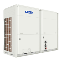
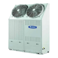
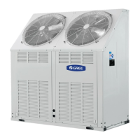
Gree LSQWF65M/N-M User Manual

Gree LSQWF65M/N-M
58 pages
To Next Page IconTo Next Page
To Previous Page IconTo Previous Page
Page #29 background imageLoading...
Page #29 background image
AIR COOLED SCROLL CHILLER INSTALLATION
26
9.2 Electric Wiring Design
Main Module ELECTRIC
BOX
Main Board
PC
X2
X3
L1 L2 L3 N 34 35 N 8 11 N 12
TB1 TB2 TB3 TB4
Main Module Terminal
POWER
WATER FLOW SWITCH
accessorial
Heater
PUMP
Module1 ELECTRIC BOX
X2
X3
L1 L2 L3 N 34 35 N 8 11 N 12
TB1 TB2 TB3 TB4
X2
X3
L1 L2 L3 N 34 35 N 8 11 N 12
TB1 TB2 TB3 TB4
Display
Board
485
A
B
COMP
To module3......
until the last
module
Module1 Terminal Module2 Terminal
Module2 ELECTRIC BOX
POWER POWER
+24V
GND
LN
L1 N
220V~ 50Hz
Main Board
PC
Main Board
PC
Assisted Board PCO

Questions and Answers:

Question and Answer IconNeed help?

Do you have a question about the Gree LSQWF65M/N-M and is the answer not in the manual?

Gree LSQWF65M/N-M Specifications

General IconGeneral
BrandGree
ModelLSQWF65M/N-M
CategoryChiller
LanguageEnglish

Related product manuals