AIR COOLED SCROLL CHILLER CONTROL
18
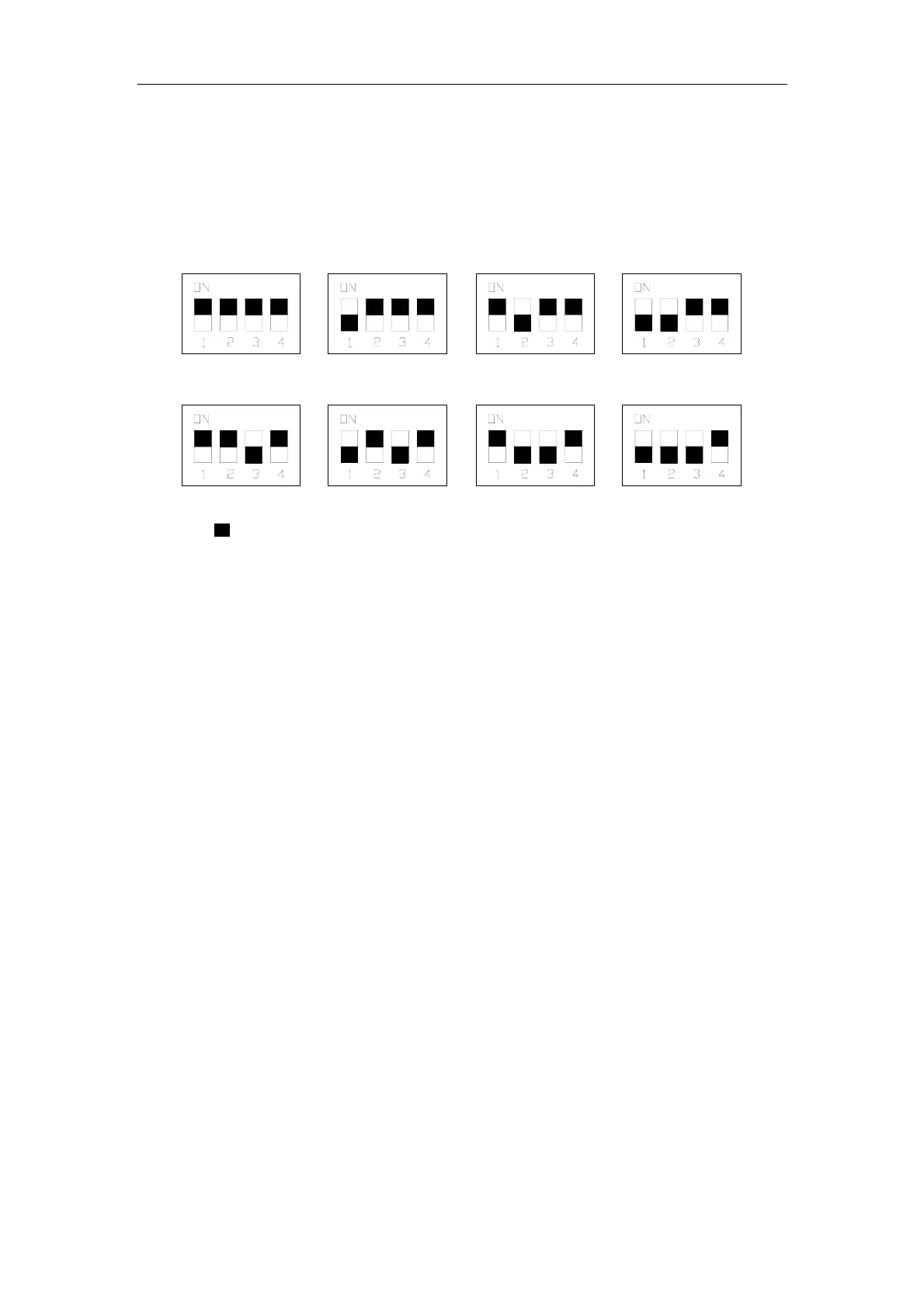
3.5 Sketch map of DIP switch
Address DIP switches setting is shown as below (Address DIP switch1, 2 and 3 are to set the
main module and sub-module)
Main module Sub-module 1 Sub-module 2 Sub-module 3
Sub-module 4 Sub-module 5 Sub-module 6 Sub-module 7
Note: “ ”on the address switch indicates the actual location of code switch.
Warning:The setting of the address DIP switch should be done while the units are powered off. If
power on, adjusting the address DIP switch is prohibited.
 Loading...