Do you have a question about the Gree FXB5A-K and is the answer not in the manual?
Provides detailed technical specifications for outdoor units, indoor units, and BU modules.
Details the control logic for outdoor units, including cooling, dry, heating, and protection functions.
Provides essential safety and installation precautions before starting the process.
Covers the installation procedures and precautions for the outdoor unit.
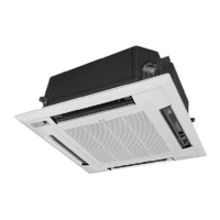
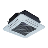
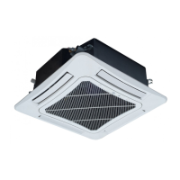
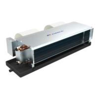
Covers the installation of various indoor unit types.
Covers the installation of BU modules.
Provides guidance for troubleshooting common issues with the unit.
| Refrigerant | R410A |
|---|---|
| Cooling Capacity | 12000 BTU/h |
| Heating Capacity | 12000 BTU/h |
| Operating Temperature (Heating) | -15°C to 24°C |
| Features | Wi-Fi Control, Sleep Mode |