EasyManua.ls Logo

Gree GFH(09)EA-K6DNA1B/I - Wiring of the Signal Line of the Wired Controller; Electric Installation; Ⅳ Rated Working Conditions

Gree GFH(09)EA-K6DNA1B/I
90 pages
To Next Page IconTo Next Page
To Previous Page IconTo Previous Page
Loading...
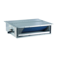
Unitary Duct Split Unitary Duct Split
19
3) Insert the signal line to the four-pin socket on the printed circuit board of the
indoor unit.
4) Fix the signal line with the binding wire.
18 Electric Installation
Table 7
Indoor Unit
Power Cord
Running
Current
(A)
Input Power(W)
Recommended
Power Cord
(Sectional
Area× Pieces)
Type
Model
Indoor
Fan
Motor
Cooling
Heating
Cooling
and
Heating
GFH(09)EA-K6DNA1B/I
220-240V~
50Hz
0.406
75
575 1.0×4
GFH(12)EA-K6DNA1B/I
220-240V~
50Hz
0.348
65
865
1.0×4
GFH(18)EA-K6DNA1B/I
220-240V~
50Hz
0.428
80
1080
1.0×4
GFH(21)EA-K6DNA1B/I
220-240V~
50Hz
0.588
110
1610 1.0×4
GFH(24)EA-K6DNA1B/I
220-240V~
50Hz
0.588
110
1610 1.0×4
Notes
The sectional area listed above is applicable to the power cord with at most a
length of 15 meters. For the longer cord, its sectional area should be enlarged to avoid
the cord burning out caused by the over-current.
Rated Working Conditions
Table 8 Working Temperature Range
Indoor side state
Outdoor side stae
Dry bulb temp.
Wet bulb temp.
Dry bulb temp.
Wet bulb temp.
Rated Cooling
27
19
35
24
Max. cooling
32
23
48
26
Min. cooling
21
15
18
Rated Heating
20
15
7
6
Max. heating
27
24
18
Min. heating
20
15
15
16
17 Wiring of the Signal Line of the Wired Controller
1) Open the cover of the electric box of the indoor unit.
2) Let the signal line go through the rubber ring.

Table of Contents

Related product manuals