GMV5 D.C INVERTER MULTI VRF SERVICE MANUAL
102
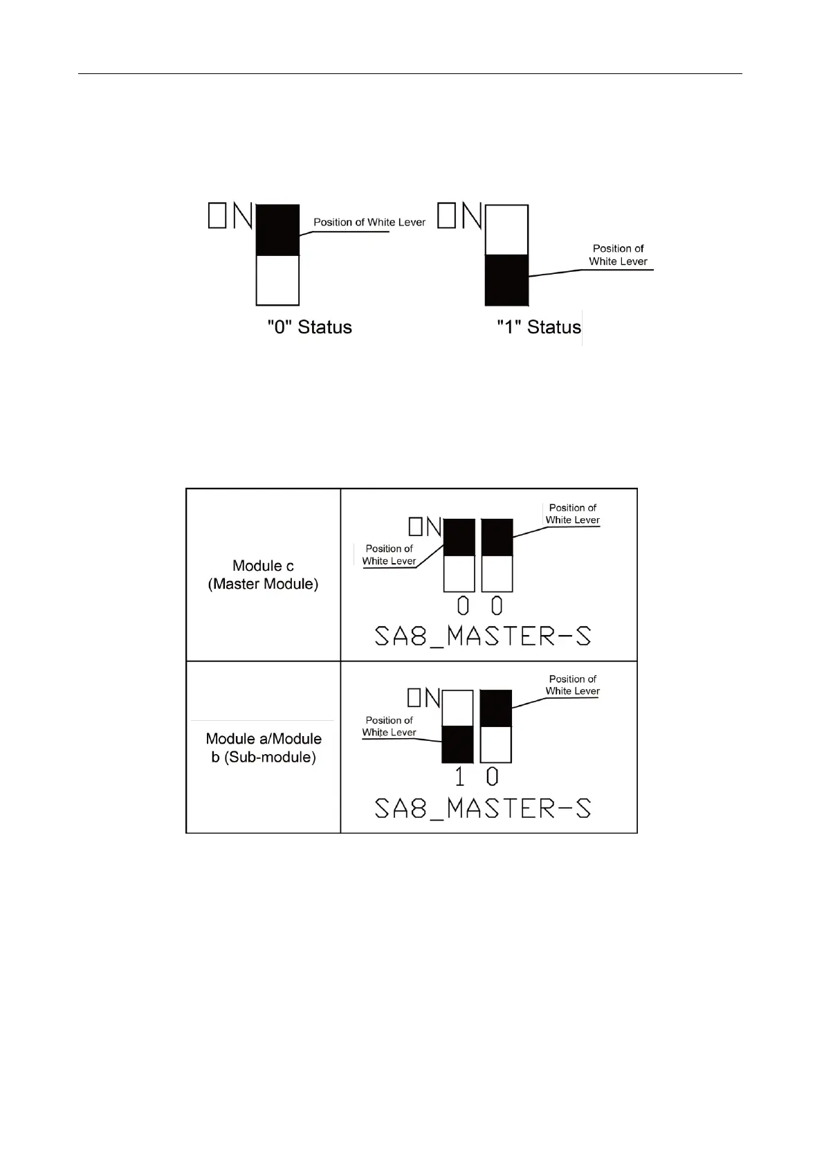
1.3.1.9 DIP Switch Example
(1) Explanation of DIP switch positions
On the DIP switch, ―ON‖ indicates ―0‖ status and the opposite direction indicates "1‖ status.
The position of white lever indicates the position to be set to.
(2) Example
The following takes master unit settings as an example. Assume that a system consists of three
modules: module a, module b, and module c. Set module c to master unit and the other two modules to
sub-modules. The settings are as follows:
1.3.2 System Function Button Operations
Note:
① System function settings and query must be performed after commissioning of the entire unit.
② System function settings and query can be used no matter whether the entire unit runs.
 Loading...
