GMV5 D.C INVERTER MULTI VRF SERVICE MANUAL
202
In some cases, the created project number is identical to that of a unit within the network. In this
case, you can use the ―one-key IDU project number reset‖ function. However, this function will cause the
project number of the entire system to be re-distributed; thus, original number will be changed. If you do
not expect this result, forbid the use of this function and replace the AP1 again.
Methods to use the ―one-key IDU project number reset‖ function:
Method 1: If the IDU is configured with wired control, set P45 to reset IDU project number through
one key function.
Method 2: If the IDU is configured with lamp board, use the special control YV1L1 to set P45 and
reset IDU project number through one key function.
Method 3: On the AP1 of the master ODU, press and hold SW5 for 10 seconds at least to clear all
project numbers of the IDUs and then redistribute project numbers. Other parameters are kept
unchanged.
After replacing the main board of master indoor unit, the master indoor unit must be reset.
3.1.2.4 Cautions on Replacement of Slave IDU AP1
If the AP1 of a slave IDU needs to be replaced, after it is powered on, ―Project number conflict (C5)‖
alarm may be reported. Refer to section 2.3 ―Cautions on Replacement of Master IDU AP1‖ to address
the issue.
3.1.3 Cautions on Wired Control Replacement
3.1.3.1 Cautions on Wired Control XK46 Replacement
(1) If the wired control to be replaced controls only one IDU, directly replace the control.
(2) If the wired control to be replaced controls multiple IDUs, perform the steps below first:
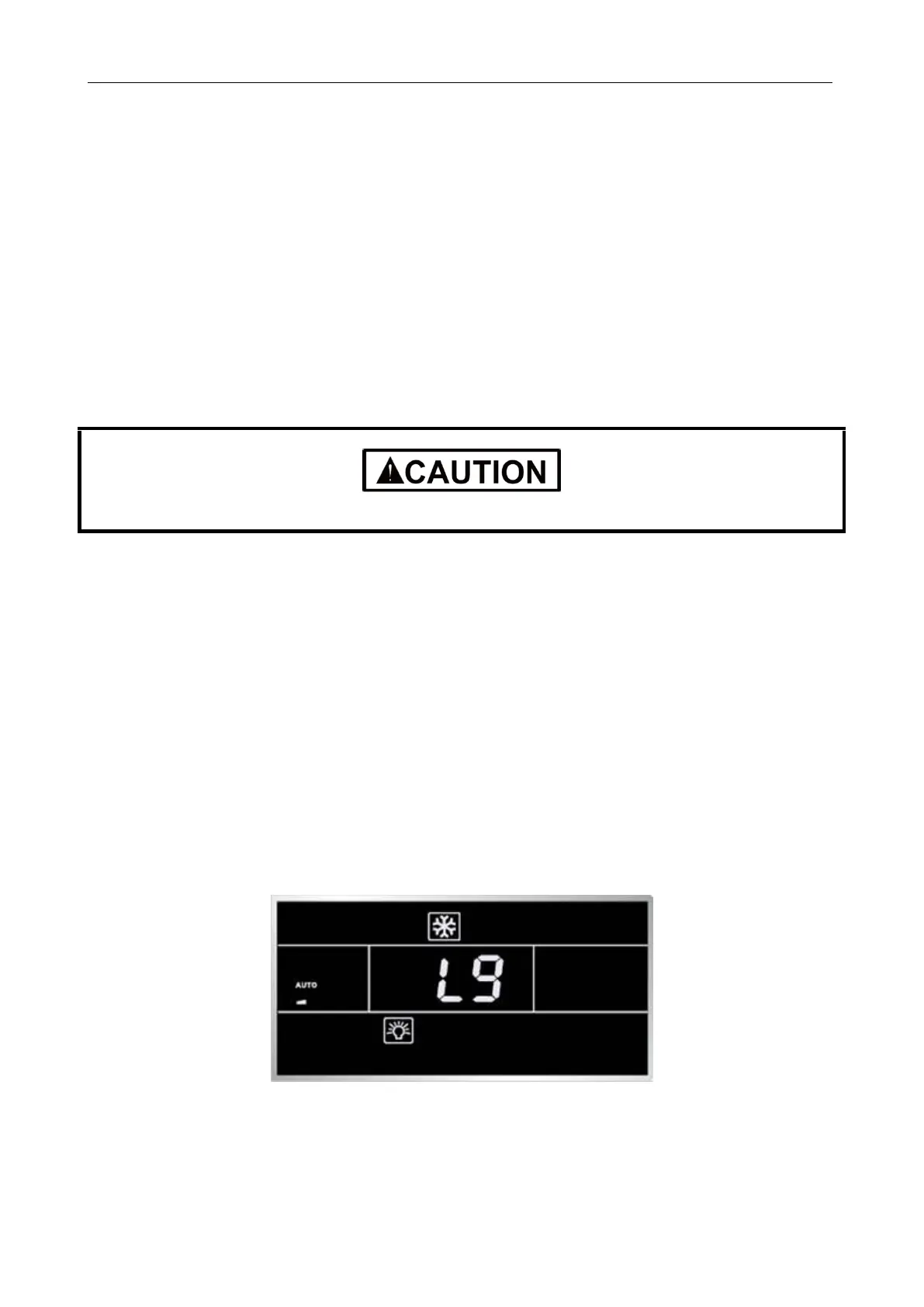
Set the wired control parameter ―P14‖ to change the number of managed IDUs to the actual quantity
the control manages. For example, if the wired control manages 3 IDUs, set this parameter to 3. If you
keep the default value 1, the LCD displays L9 (as shown in the figure below).
(3) If there are two wired controls controlling one or multiple IDUs, perform the steps below first:
Set the wired control parameter ―P13‖ to change the address of one control to 01 (master) and that
of the other control to 02 (slave); otherwise, a CP (multiple master wired controls) fault alarm will be
reported (as shown in the figure below).
 Loading...
