GMV5 D.C INVERTER MULTI VRF SERVICE MANUAL
209
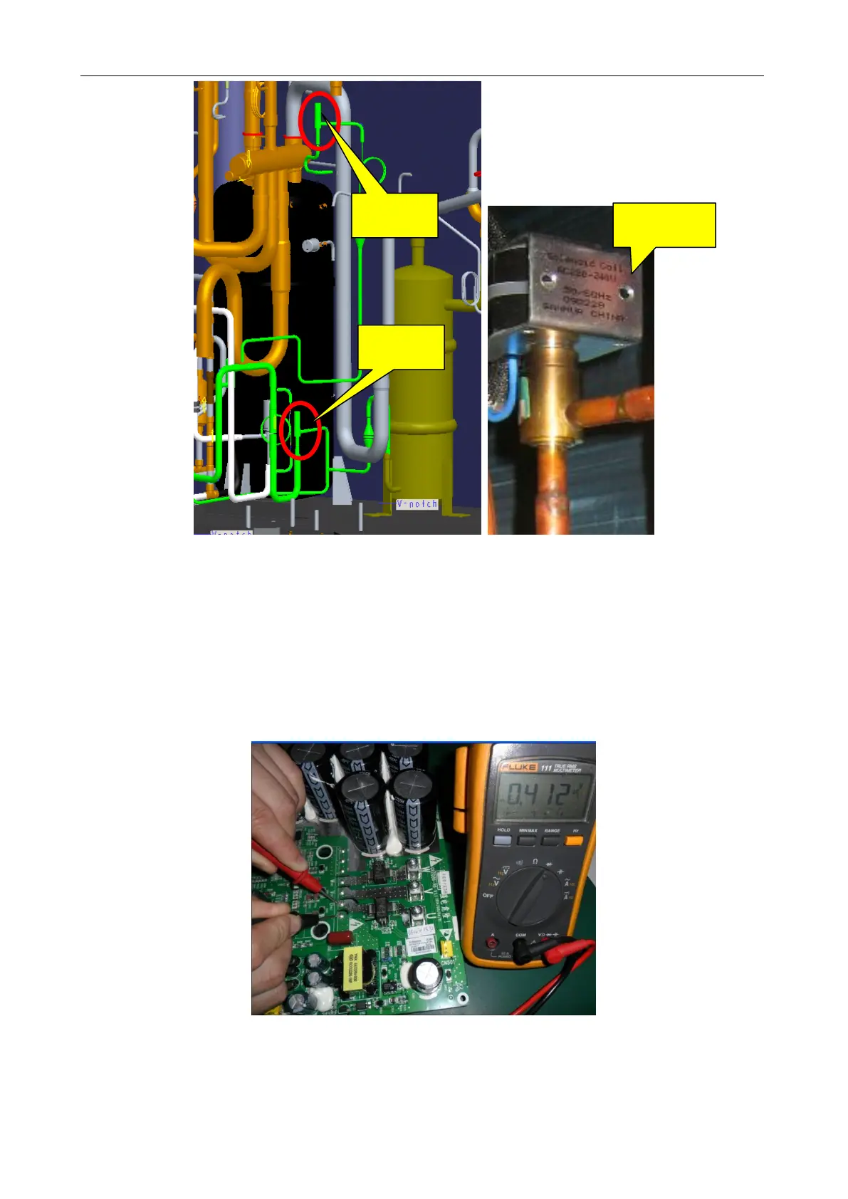
Step 4:
Test the compressor drive, namely the IPM module, to see whether it is normal.
1) Disconnect the power supply. Five minutes later, remove the line of the faulty compressor.
2) Set a multimeter to gear diode. As shown in the figure below, put the black test probe to pad P
(on the left of pad U (BL)) and the red test probe to pad U (BL) (make sure the moisture proof tape is
removed). In normal cases, the multimeter should read 0.39±0.3 V. If it is ―0‖ or infinitely great, the IPM
module is faulty.
3) As shown in the figure below, put the black test probe to pad P and the red test probe to pad V
(YE) (make sure the moisture proof tape is removed). In normal cases, the multimeter should read
0.39±0.3 V. If it is ―0‖ or infinitely great, the IPM module is faulty.
 Loading...
